600 series Snowthrowers IMPORTANT: Read safety rules and instructions carefully before operating equipment. 60 OTTAWA STREET SOUTH, KITCHENER, ONTARIO N2G 3S7 Printed in U.S.A. FORM NO.
TABLE OF CONTENTS Content Customer Support Important Safe Operation Practices Setting Up Your Snowthrower Knowing Your Snowthrower Operation Adjustments Page 2 3 5 8 10 13 Content Maintenance & Service Off Season Storage Trouble Shooting Warranty Illustrated Parts List Page 15 19 20 21 22 FINDING MODEL NUMBER This Operator’s Manual is an important part of your new snow thrower. It will help you to assemble, prepare and maintain the unit for best performance. Please read and understand what it says.
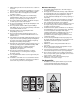
SECTION 1: IMPORTANT SAFE OPERATION PRACTICES WARNING: This symbol points out important safety instructions which, if not followed, could endanger the personal safety and/or property of yourself and others. Read and follow all instructions in this manual before attempting to operate this machine. Failure to comply with these instructions may result in personal injury. When you see this symbol—heed its warning.
7. 8. 9. 10. 11. 12. 13. 14. 15. 16. 17. 18. 19. 20. Maintenance And Storage Muffler and engine become hot and can cause a burn. Do not touch. Exercise extreme caution when operating on or crossing gravel surfaces. Stay alert for hidden hazards or traffic. Exercise caution when changing direction and while operating on slopes. Plan your snow throwing pattern to avoid discharge towards windows, walls, cars etc. To avoid property damage or personal injury caused by a ricochet.
SECTION 2: SETTING UP YOUR SNOW THROWER NOTE: If the connector is not properly assembled, the shift rod will pivot and changing speed or direction of the snow thrower will not be possible. NOTE: The snow thrower is shipped with oil and WITHOUT GASOLINE. After assembly, refer to separate engine manual for proper fuel and engine oil recommendations. Unpacking • • • Cut along corners of the carton and lay it down flat. Remove packing material. Remove any loose parts included with unit (i.e.
Chute Assembly (all models) Cables 1. Apply a light lubricant (i.e. 3-in-1 oil) to the base of the chute assembly. 2. Place the chute assembly on the lip of the chute adapter. See Figure 3 3. One end of each chute keeper is already attached to the chute flange. Pivot the free end of the chute keeper to align it with the chute flange and push it till it snaps into position. See Figure 4. Repeat with remaining chute keepers. Short Tube Chute Support Tube Figure 6 Chute Assembly 2 2.
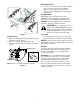
Chute Clean-out Tool 1. The chute clean-out tool is fastened with a cable tie to the rear of the auger housing for shipping purposes. Cut the cable tie and remove the extension cord (if equipped) before operating the snow thrower. Final Adjustments After setting up your snow thrower, check the adjustments as instructed below and make any final adjustments necessary before operating the unit. CAUTION: Failure to comply with these adjustment instructions may cause damage to the unit.
SECTION 3: KNOWING YOUR SNOW THROWER Drive Control Shift Lever Auger Control Electric Starter Button Engine Controls Gas Cap Recoil Starter Handle Oil Fill Electric Starter Outlet Chute Assembly Primer Clean-out Tool Ignition Key Chute Directional Control Choke Control Shave Plate Throttle Control Skid Shoe Augers Figure 10 WARNING: Read, understand, and follow all instructions and warnings on the machine and in this manual before operating.
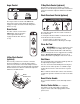
Auger Control 2 Way Chute Control (optional) This two-way control lever is meant to control the distance of snow discharge from the chute. Tilt the lever forward or rearward to adjust the distance snow will be thrown. Chute Directional Control (optional) CHUTE DIRECTIONAL CONTROL COMMANDE D'ORIENTATION DE LA GOULOTTE The auger control is located on the left handle. Squeeze the auger control against the handle to engage the augers and start snow throwing action. Release to stop.
Electric Starter Outlet (If so equipped) Augers Requires use of a three-prong outdoor extension cord (packed with the snow thrower) and a 120V power source/wall outlet. When engaged, the augers rotate and draw snow into the housing. Chute Assembly Snow drawn into the auger housing is discharged out the chute assembly.
NOTE: If the engine is already warm, place choke Pulling the starter rope will produce a loud clattering sound, which is not harmful to engine. 2. Move throttle control to STOP position. 3. Remove the ignition key. control in the OFF position instead of FULL. • Push the primer two or three times for cold engine start, making sure to cover vent hole in the center of the primer when pushing. NOTE: Keep the key in a safe place. The engine cannot start without the ignition key.
Auger Control Test IMPORTANT: Perform the following test before operating your snow thrower for the first time and at the start of each winter season. Z Fitting Hex Nut Check the adjustment of the auger control as follows: • • • • • • When the auger control is released and in the disengaged “up” position, the cable should have very little slack. It should NOT be tight.
Chute Clean-Out Tool . The chute clean-out tool is conveniently fastened to the rear of the auger housing with a mounting clip. Should snow and ice become lodged in the chute assembly during operation, proceed as follows to safely clean the chute assembly and chute opening: • • • • Release both the Auger Control and the Drive Control. Stop the engine by removing the ignition key. Remove the clean-out tool from the clip which secures it to the rear of the auger housing.
SECTION 5: MAKING ADJUSTMENTS WARNING: Never attempt to make any adjustments while the engine is running, except where specified in operator’s manual. 3 Shift Rod Adjustment Chute Assembly If the full range of speeds (forward and reverse) cannot be achieved, refer to the figures to the right and adjust the shift rod as follows: 1 Thread the ferrule up or down the shift rod until it aligns with the hole in the shift lever behind the handle panel.
. Figure 18 Figure 17 Skid Shoes Drive Control NOTE: The space between the skid shoes and the ground can be adjusted. See Figure 19. For close snow removal, place skid shoe in the low position. Use middle or high position when area to be cleared is uneven. When the drive control is released and in the disengaged “up” position, the cable should have very little slack. It should NOT be tight. Check the adjustment of the drive control as follows: 1.
SECTION 6: MAINTAINING AND SERVICING YOUR SNOW THROWER WARNING: Before lubricating, repairing, or the spacers. Also lubricate the flange bearings found at either end of the shaft. See Figure 21. inspecting, disengage all controls and stop engine. Wait until all moving parts have come to a complete stop. Engine Spacers Bearing Bearing Refer to the separate engine manual packed with your unit for all engine maintenance. Lubrication Engine Refer to the separate engine manual packed with your unit.
• • • To remove skid shoes, remove the four carriage bolts and hex flange nuts which secure them to the snow thrower. Reassemble new skid shoes with the four carriage bolts (two on each side) and hex flange nuts. Refer to Figures 19 and 21. To remove shave plate, remove the carriage bolts, cupped washers and hex nuts which attach it to the snow thrower housing. Reassemble new shave plate, making sure heads of carriage bolts are to the inside of housing. Tighten securely.
• • • Push idler away from the chute and insert a Philips head screwdriver in the hole on the idler as shown in Figure 26. This will release tension on drive belt. Drive Belt Engine Pulley Auger Belt Friction Wheel Rubber • Idler • • • • • Figure 26 • • • • Pull drive belt out and away from the engine pulley to remove. See Figure 26. Tip the snow thrower up and forward, so that it rests on the housing.
3 Plate 2 Friction Wheel Rubber 1 Screw 4 Figure 29 Figure 28 SECTION 7: OFF-SEASON STORAGE If unit is to be stored over 30 days, prepare for storage as instructed in the separate engine manual packed with your unit. • • • WARNING: Never store snow thrower with fuel in tank indoors or in poorly ventilated areas, where fuel fumes may reach an open flame, spark or pilot light as on a furnace, water heater, clothes dryer or gas appliance.
SECTION 8: TROUBLE SHOOTING Problem Cause Remedy Engine fails to start. 1. 2. 3. 4. 5. 6. 7. Engine runs erratic. 1. Unit running on CHOKE. 2. Blocked fuel line or stale fuel. Fuel tank empty, or stale fuel. Blocked fuel line. Choke not in ON position Faulty spark plug. Safety key not in ignition switch on engine. Spark plug wire disconnected. Primer button not being used properly. 3. Water or dirt in fuel system. 4. Carburetor out of adjustment. Loss of power. 1. 2. 3. 4. 5. 6. 7.
SECTION 9: THREE (3) YEAR LIMITED WARRANTY For three (3) years from the date of original purchase of our products, we will either repair or replace, at its option, free of charge, F.O.B. Factory or authorized service firm, any part found to be DEFECTIVE IN MATERIAL and WORKMANSHIP for the original purchaser. all transportation charges on parts submitted for replacement under this warranty must be paid by the purchaser unless return is requested by the manufacturer.