ATTACHMENT No R e t fo pro r du cti on OPERATOR’S MANUAL 42” Single-Stage Snowthrower Model No. Description 1695969 42” Single Stage Snowthrower Copyright © 2011 Briggs & Stratton Power Products Group, LLC Milwaukee, WI, All rights reserved.
No R e t fo pro r du cti on
Table of Contents Table of Contents 4 4 5 6 6 6 6 7 7 7 8 8 8 8 9 9 9 10 10 10 11 12 12 14 15 16 17 17 17 17 18 18 18 18 19 19 20 20 20 20 21 21 21 22 No R e t fo pro r du cti on Hardware ........................................................................................ Bag Contents ............................................................................ Box Contents ............................................................................. Operator Safety ....................................
Hardware Bag Contents A - HITCH SUPPORT SHAFT B - HITCH LATCH PIN C - COTTER PIN D - HAIR PIN I - SWITCH G - SPRING H - AXLE CLAMP No R e t fo pro r du cti on F - TURNBUCKLE E - SAFETY CLIP (Qty. 2) J - UPPER WIRE HARNESS K - EXTENSION WIRE HARNESS - 26” L - CLIPS (Qty. 4) M - REFLECTORS (Qty.
Hardware Box Contents O - LIFT ARM ASSEMBLY No R e t fo pro r du cti on N - CHUTE P - HITCH ASSEMBLY Q - LIFT ROD ASSEMBLY R - SNOWTHROWER 5
Operator Safety WARNING This machine is capable to amputating hands and feet and throwing objects. Read these safety rules and follow them closely. Failure to obey these rules could result in loss of control of unit, severe personal injury or death to you, or bystanders, or damage to property or equipment. The triangle in text signifies important cautions or warnings which must be followed. OPERATION TRAINING 1.
Operator Safety 15. Never operate the snowthrower without good visibility or light. Always be sure of your footing, and keep a firm hold on the handles. Walk, never run. 16. Never touch a hot engine or muffler. 17. Never operate the snowthrower near glass enclosures, automobiles, window wells, drop-offs, and the like without proper adjustment of the discharge angle. 18. Never direct discharge at bystanders or allow anyone in front of the unit. 19. Never leave a running unit unattended.
Operator Safety Accessories Safety Decals Accessories This unit has been designed and manufactured to provide you with the safety and reliability you would expect from an industry leader in outdoor power equipment manufacturing.
Features and Controls C A B E No R e t fo pro r du cti on D Control Functions Tractor Controls The information below briefly describes the function of individual controls. Operating the tractor and attachment requires the combined use of these controls and additional controls whose operation is described in the tractor Operator’s Manual.
Assembly Unpacking 1. Position box close to the tractor and carefully unpack and organize snowthrower parts. 3. Align chute (N, Figure 3) notch (*) on chute with housing chute ring tab (**) and slide chute into place. IMPORTANT: See Figure 1 for correct orientation of snow drive pulley hub. 2. If snow drive pulley hub orientation is incorrect, loosen set screw, remove and flip pulley to correct orientation and tighten set-screw. N * ** Figure 3 4. Rotate chute 180 degrees to front.
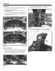
Assembly 5. Loosen the three nuts (*, Figure 5) on motor assembly. Replace chute rotator gear (**) onto shaft and mesh the teeth with chute ring gear (***). Slide motor assembly forward and tighten the hex bolts (*). 4. On underside of tractor frame, locate 11/16” holes approximately 14” forward from rear tire. Insert hitch support shaft (A, Figure 7). Secure with the cotter pin (C) on inside of frame and slightly bend longest leg up.
Assembly 6. Lift front of the hitch assembly (P, Figure 8) up to tractor hook-hitch (*). 4. Install the drive belt onto the snowthrower drive pulley (*, Figure 10) and then onto the tractor PTO pulley (**). 7. Slide hitch latch pin (B) through the mounting holes in the hitch frame. Secure hitch latch pin with the hair pin (D). NOTE: Keep the handle portion of the hitch latch pin towards the front of the tractor. ** * B D * Figure 10 No R e t fo pro r du cti on 5.
Assembly 2. Attach lift arm assembly (O, Figure 13) to the tractor frame using the four hex bolts (*) and nuts from the previous step. * * 5. Assemble lift assist parts. Attach spring (G, Figure 15) to turnbuckle (F) and axle clamp (H). NOTE: Do not position the axle clamp over the axle rib. F G H Figure 15 O Figure 13 3. Install lift rod assembly (Q, Figure 14) and secure with safety clips (E). 6. Fully raise the snowthrower off the ground. 7.
Assembly Attach Chute Motor Wiring Harness (Non-Electric Deck Lift Models) NOTE: Open hood on tractor for installing the wire harness. 1. Remove plug from tractor dashboard (*, Figure 18). 4. Locate the tractor power leads (Figure 21), red with yellow stripe (*) and black (**), at the base of steering column. Connect these leads, color to color, to the upper wiring harness (J). IMPORTANT: DO NOT use yellow and black power tractor lead. J * * Figure 18 ** No R e t fo pro r du cti on 2.
Assembly 7. Secure wiring harness in place with clips (L, Figure 23) to the frame rails. NOTE: Wire harness slack should be secured and not interfere with moving parts. Attach Chute Motor Wiring Harness (Electric Deck Lift Models) 1. Under right rear fender, locate and disconnect the electric height of cut motor plug (*, Figure 25). L * Figure 25 2. Plug white female connector end of 26” extension wire harness (K, Figure 26) into existing tractor wire harness.
Assembly 4. Connect chute rotation wire harness (*, Figure 28) to the 26” extension wire harness (K). Install Reflectors Install the two reflectors (M, Figure 30) on the rear of the tractor seat deck M K * Figure 28 7. Secure wiring harness in place with clips (L, Figure 29) to the frame rails. L Figure 29 16 Figure 30 No R e t fo pro r du cti on NOTE: Wire harness slack should be secured and not interfere with moving parts.
Operation WARNING If auger does not start and stop when engaging/ disengaging electric clutch, see your authorized dealer. Under no circumstances should you attempt to defeat the safety system. Checks Before Starting 1. Refer to the Maintenance & Adjustments sections of this manual and perform any needed service. Also, refer to the tractor Operator’s Manual and perform any required service. 2. Remove any objects from the work area which might be caught in, or thrown by, the auger. 3.
Operation Storage Snow Removal Suggestions Daily Storage • Determine the best snow removal pattern before beginning. 1. Run the snowthrower a few minutes after blowing snow to prevent freeze-up of auger. • Wind direction is an important factor to consider. Rotate the spout to discharge snow downwind. 2. Allow tractor engine to cool before storing in any enclosure. • Plan the pattern so that you avoid throwing snow on cleared areas and on yourself as you are operating.
Troubleshooting Troubleshooting While normal care and regular maintenance will extend the life of your equipment, prolonged or constant use may eventually require that service be performed to allow it to continue operating properly. The troubleshooting guide below lists the most common problems, their causes and remedies. See the information on the following pages for instructions on how to perform most of these minor adjustments and service repairs yourself.
Troubleshooting Skid Shoe Adjustment Lift Adjustment On smooth surfaces such as concrete or asphalt, the scraper bar should scrape the surface. On surfaces such as gravel, the scraper bar should be set high enough so that it will not pick up debris. In the fully raised position the attachment should be 4”-5” off the ground. 1. Loosen the nuts securing the skid shoes (*, Figure 31). 1. Fully raise the attachment lift. The snowthrower should be approximately 4”-5” off the ground. If not, go to step 2.
Maintenance WARNING To avoid serious injury, perform maintenance on the unit only when the engine is stopped and all moving parts have stopped. Always remove the ignition key before beginning maintenance or adjustments to prevent accidental starting of the engine. Maintenance Schedule Care Required Schedule Clean snow and ice from unit. After each use. Lubricate snowthrower. Every 10 hours or at least once a year. General Lubrication Lubricate the snow thrower as shown in Figure 28.
Warranty BRIGGS & STRATTON POWER PRODUCTS GROUP, L.L.C. OWNER WARRANTY POLICY LIMITED WARRANTY Briggs & Stratton Power Products Group, LLC will repair and/or replace, free of charge, any part(s) of the equipment that is defective in material or workmanship or both. Briggs & Stratton Corporation will repair and/or replace, free of charge, any part(s) of the Briggs and Stratton engine* (if equipped) that is defective in material or workmanship or both.
No R e t fo pro r du cti on
No R e t fo pro r du cti on Copyright © 2011 Briggs & Stratton Power Products Group, LLC Milwaukee, WI, All rights reserved.