Safety • Assembly • Operation • Tips & Techniques • Maintenance • Troubleshooting • Parts Lists • Warranty OPERATOR’S MANUAL Single-Stage Snow Thrower IMPORTANT READ SAFETY RULES AND INSTRUCTIONS CAREFULLY BEFORE OPERATION Warning: This unit is equipped with an internal combustion engine and should not be used on or near any unimproved forest-covered, brushcovered or grass-covered land unless the engine’s exhaust system is equipped with a spark arrester meeting applicable local or state laws (if any).
This Operator’s Manual is an important part of your new snow thrower. It will help you assemble, prepare and maintain the unit for best performance. Please read and understand what it says. Table of Contents Safety Labels............................................ p. 3 Safe Operation Practices........................ p. 4 Setting Up Your Snow Thrower............... p. 6 Know Your Snow Thrower....................... p. 7 Operating Your Snow Thrower................ p.
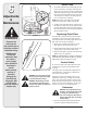
1 FOR TURNING, NOT LIFTING Safety Labels AVOID INJU RY FROM ROTAT I N G A U G E R KEEP HANDS , FEET AND CLOTHING AWAY. DANGER WARNING NEVER PUT HAND IN CHUTE. CONTACT WITH ROTATING PARTS CAN AMPUTATE FINGERS AND HANDS. SHUT OFF ENGINE AND WAIT UNTIL AL L MOVING PARTS HA VE STOPPED BEFORE UNCLOGGING. USE CLEAN-OUT TOOL OR WOODEN STICK TO UNCLOG DISCHARGE CHUTE. 1. KEEP AWAY FROM RO TATING AUGER CONTACT WITH AUGER CAN AMPU TATE HANDS AND FEE T. 2.
2 Safe Operation Practices WARNING This symbol points out important safety instructions which, if not followed, could endanger the personal safety and/or property of yourself and others. Read and follow all instructions in this manual before attempting to operate this machine. Failure to comply with these instructions may result in personal injury. When you see this symbol.
Operation Maintenance & Storage 1. Do not put hands or feet near rotating parts, in the auger/impeller housing or chute assembly. Contact with the rotating parts can amputate hands and feet. 2. The auger/impeller control lever is a safety device. Never bypass its operation. Doing so makes the machine unsafe and may cause personal injury. 3. The control levers must operate easily in both directions and automatically return to the disengaged position when released. 4.
3 NOTE: This Operator’s Manual covers several models. Snow thrower features vary by model. Not all features discussed in this manual are applicable to all snow thrower models. 1 NOTE: All references to left or right side of the snow thrower is from the operating position only Snow Thrower Setup Contents of Carton Carton contents are listed below with part numbers in parentheses. 1. Two Ignition Keys (725-0201) 2 2. 20 oz. Bottle 5-30W Oil (737-0209) 3.
4 Auger Control Handle Recoil Starter Know Your Snow Thrower Key Primer Gasoline Cap Electric Starter Button Chute Assembly Choke Lever Spark Plug Access Shave Plate Oil Fill Auger IMPORTANT: This unit is shipped without oil in the engine. Oil is packaged separately with this unit and must be added per the engine owner’s manual instructions. Figure 4-1 Choke Lever OFF Auger CHOKE ON Activating choke control closes the choke plate on carburetor and aids in starting engine.
5 Operation Recoil Starter Key Primer Gasoline Cap Electric Starter Button WARNING WARNING: Read, understand, and follow all instructions and warnings on the machine and in this manual before operating. Use extreme care when handling gasoline. Gasoline is extremely flammable and the vapors are explosive. Never fuel the machine indoors or while the engine is hot or running. Extinguish cigarettes, cigars, pipes and other sources of ignition.
10. When engine starts, release starter button, and move choke gradually to 1/2 Choke until the engine runs smoothly. Next move Choke to OFF. If engine falters, move choke immediately to FULL and then gradually to 1/2 then to OFF. 11. Disconnect the power cord. Always unplug from the outlet first, and then from the snow thrower. Recoil Starter 1. Move choke lever to FULL choke position (cold engine start). 2. If engine is warm, place choke in OFF position instead of FULL. 5.
6 Shave Plate Side View Adjustments & Maintenance NOTE: On new units or units with a new shave plate installed, the augers may be slightly off the ground. 2. To adjust, tip the snow thrower back so that it rests on the handle. Loosen the four lock nuts and bolts which secure the shave plate to the housing. See Figure 6-1. Move the shave plate to desired position and retighten the nuts and bolts securely.
Replacing Belt WARNING: Before servicing, repairing, or inspecting, disengage the control bail and stop engine. Wait until all moving parts have come to a complete stop. Disconnect spark plug wire and ground it against the engine to prevent unintended starting. Idler Pulley Remove the belt cover by removing five hex screws. See Figure 6-3. Then simply pull the belt off by grasping it from the bottom of the auger pulley and pulling off.
7 Off-Season Storage WARNING Never store snow thrower with fuel in tank indoors or in poorly ventilated areas, where fuel fumes may reach an open flame, spark or pilot light as on a furnace, water heater, clothes dryer or gas appliance. Drain fuel into an approved container outdoors, away from any open flame. Be certain engine is cool. Do not smoke. Fuel left in engine during warm weather deteriorates and will cause serious starting problems. Do not drain carburetor if using fuel stabilizer.
Possible Cause(s) Problem Engine fails to start 1. 2. 3. 4. 5. Fuel tank empty, or stale fuel Blocked fuel line Key not in ON position Spark plug wire disconnected Faulty spark plug 6. Engine not primed 7. Engine flooded from excessive priming Engine runs erratic Engine overheats Loss of power Excessive vibration Unit fails to self-propel 1. Unit running on choke 2. Fuel line blocked, or stale fuel Fill tank with clean fresh gasoline.
Model Series 2B5-295 18 55 17 23 8 10 16 7 1 6 11 5 25 24 32 9 39 15 40 12 50 34 49 44 31 29 2 7 27 46 38 48 29 28 41 9 45 43 35 36 20 30 22 29 13 3 26 21 4 19 37 47 14 33
9 Part List: REF NO. PART No. DESCRIPTION Qty. REF NO. PART No. DESCRIPTION Qty. 1 629-0071 Extension Cord 1 26 734-04204 Wheel 5 Lug Diamond Design 2 2 710-0409 Hex Screw, 5/16-24 x 1.75 4 27 684-04168 Idler Pulley (1/4” hole) 1 3 710-0627 Hex Screw, 5/16-24 x .75 1 28 735-04033 Rubber Paddle 2 4 710-0654A Self Tapping Screw, 3/8-16 x 1 2 29 710-0896 Hex Screw, 1/4-20 x .62 24 5 710-0751 Hex Screw, 1/4-20 x .
9 35 22 36 Part List: Snow Thrower 25 18 16 24 23 6 For parts and/or accessories please call our Dealer Locator line at 1-800-949-4483 or log onto whiteoutdoor.
REF NO. PART NUMBER DESCRIPTION Qty. 1 684-04127 Chute Assembly (Incl. Ref. 37-41) 1 2 710-04071 Carriage Bolt 5/16-18 x 1.0” 1 3 710-0451 Carriage Bolt 5/16-18 x 0.750” 1 4 712-04063 Flange Lock Nut, 5/16-18 6 5 720-04072 Star Knob Assembly 1 6 731-04388A Chute Handle 1 7 731-04426A Upper Chute 1 8 731-04353 Ring-Lower Chute 1 9 710-04532 Carriage Bolt 5/16-18 x 2.0 Gr.
10 Accessories & Kits The following accessories and kits are available for single-stage, two-cycle snow throwers. See the retailer from which you purchased your snow thrower, or any authorized White Outdoor Service Dealer. To find the White Outdoor service dealer nearest you, call our dealer locator line at 1-800949-4483 or log onto www.whiteoutdoor.com.
11 NOTES: Use this page to make notes and write down important information. For parts and/or accessories please call our Dealer Locator line at 1-800-949-4483 or log onto whiteoutdoor.
MANUFACTURER’S LIMITED WARRANTY FOR The limited warranty set forth below is given by MTD LLC with respect to new merchandise purchased and used in the United States, its possessions and territories. “MTD” warrants this product against defects in material and workmanship for a period of two (2) years commencing on the date of original purchase and will, at its option, repair or replace, free of charge, any part found to be defective in materials or workmanship.