
Service manual


CONTROLS/LOCATION AND OPERATION
3 - 8 Single Stage Snowthrower Service Manual
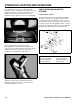
Figure 28 1352-08
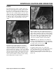
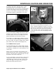
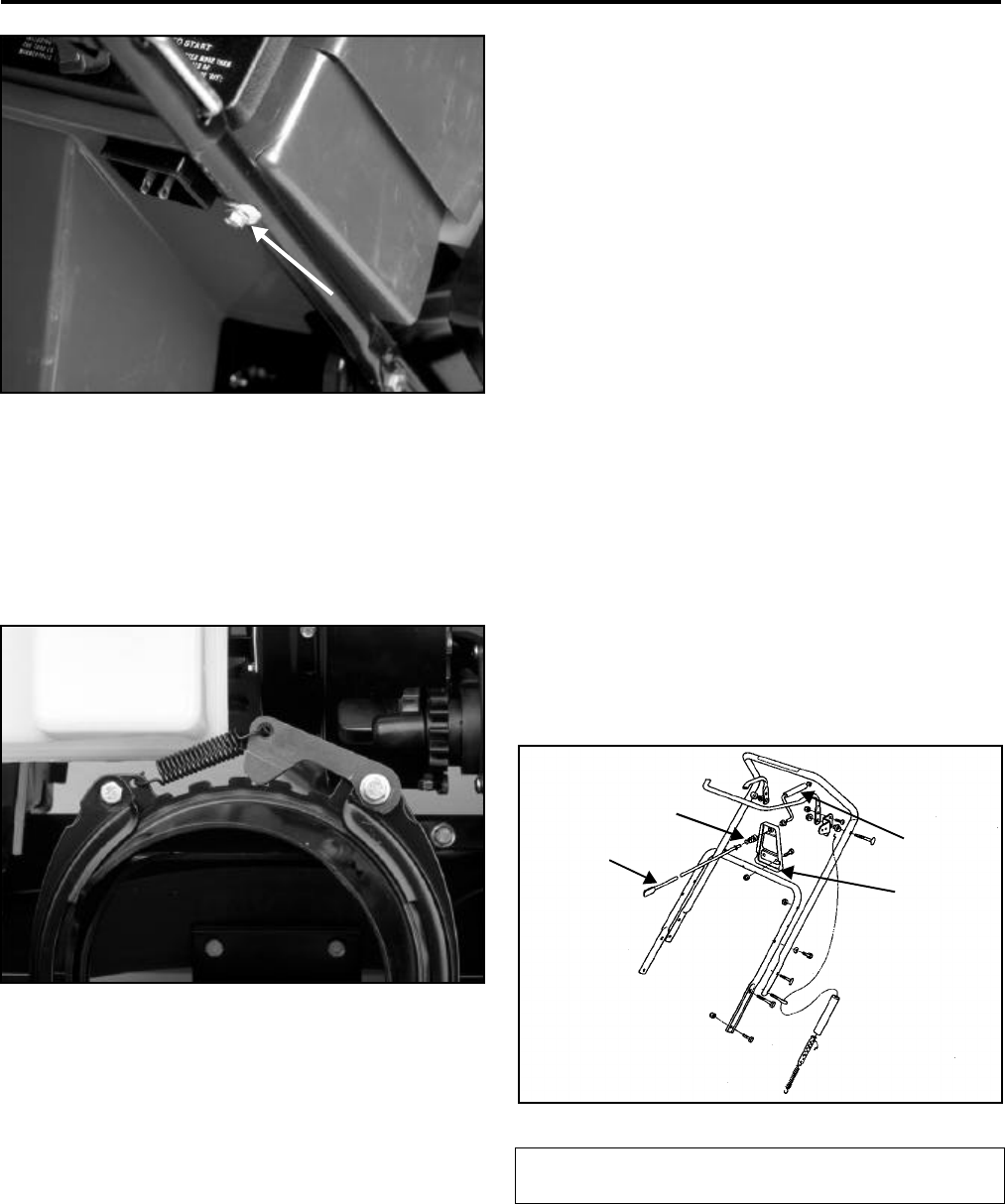
Remove the gas cap and lift the upper shroud off the
machine. Replace the gas cap to prevent fuel spillage
or dirt from entering the fuel system. Now you see the
chute ring, the two chute ring retainers, and the detent
arm and spring (Figure 29). To remove the chute ring,
remove the 4 bolts and nuts that retain the left and right
chute ring retainers.
Figure 29 1854-40
Note: The rear bolt in the left hand chute ring retainer
is also the pivot for the detent arm. This arm engages
the notches in the chute ring to prevent unwanted
rotation of the chute. With the four bolts removed, the
retainers and chute ring will then lift off.
These parts are all plastic to eliminate the need for
lubrication and resist icing.
Reassembly is the reverse of disassembly.
Note: The rounded heads of the carriage bolts must
be on the inside of the chute. The smooth head
prevents snow from building up on the bolt head.
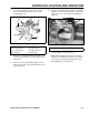
20” CCR Crank System
The third system, used on CCR2000 as well as the
2400, 2500 and 3600 series uses a crank that is
mounted to the handle.
Rotating the handle turns a set of gears that engage a
ring gear that the chute is mounted to. The gears are
contained in a bracket located under the upper shroud.
The chute ring gear rests on a support and is held in
place by two retainers. The chute retainers allow the
ring gear to rotate only.
To access the chute ring and gears:
1. Remove the 3 carriage head bolts and locknuts at
the base of the chute and lift off the chute
assembly.
2. Remove the 2 bolts and nuts that hold the chute
crank rod bracket to the lower handle and draw
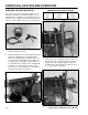
the rod out of the upper shroud (Figure 30).
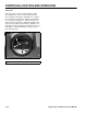
Figure 30 0309-22
(A) Crank Handle Grip
(B) Chute Crank Support
(C) Chute Crank Rod
(D) Spring
A
B
C
D