
Service manual


Single Stage Snowthrower Service Manual 3 - 9
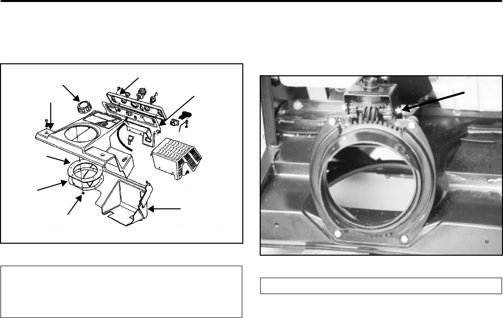
CONTROLS/LOCATION AND OPERATION
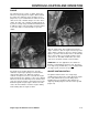
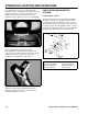
3. To remove the upper shroud, remove the two
bolts and locknuts in the front corners of the
shroud (Figure 31).
Figure 31
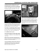
4. Remove 3 screws that hold the face plate to the
control panel and let the face plate hang from the
starter rope.
5. Remove the gas cap and lift the upper shroud,
replace the gas cap. The chute ring and gears are
now all exposed.
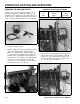
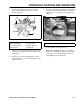
6. The gears are held in the bracket by a shaft with a
push nut on either end (Figure 32). To remove the
shaft, remove one of the push nuts and pull the
shaft out.
Figure 32 1854-19
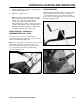
7. To reassemble, reverse the process.
Note: When installing the chute, the rounded
heads of the carriage bolts must be on the inside
of the chute. The smooth head prevents snow
from building up on the bolt head.
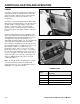
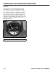
(A) Nameplate
(B) Control Panel
(C) Lower Shroud
(D) Push Nut
(E) Chute Seal Retainer
(F) Chute Seal
(G) Upper Shroud
(H) Gas Cap
A
B
C
D
E
F
G
H
(A) Shaft and Push Nut
A