
Service manual


DRIVE SYSTEMS
5 - 22 Single Stage Snowthrower Service Manual
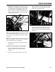
5. It will be necessary to align the keyway (slot) of
the crankshaft sprocket with the location key on
the crankshaft (Figure 111). Should the locating
key on the crankshaft show signs of wear, it may
be necessary to replace the key.
Figure 111 0217-062
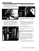
6. From the rear of the unit, visually align the
crankshaft sprocket and chain with the impeller
sprocket. Once the sprocket and chain have been
installed (Figure 112) it is essential the chain be
aligned properly. If not, crankshaft or sprocket
damage will occur. Note: Figure 112 shows an
improperly aligned chain and sprocket.
Figure 112 0217-063
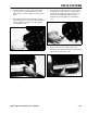
7. After aligning the chain, tighten the allen head
screws on the crankshaft sprocket (Figure 113).
Figure 113 0217-064
8. Pull the engine back until the chain is snug, with
no more than 1/8 inch deflection or slack (Figure
107).
9. Retighten the four bolts on sequence illustrated in
the Chain Adjustment procedure (Figure 108).
Torque to 170 - 220 in·lbs. Then tighten the
starter housing bolt, on the right side of the unit,
70 - 120 in·lbs. (Figure 106).
Note: Not following this tightening sequence can
lead to crankshaft breakage.
10. Replace the shrouding, chain guard, and spark
plug lead wire.
L.H. And R.H. (Left Hand And Right Hand) End Cap/
Bushing Replacement (1972-1980) 14” And 21”
Models
Note: Left hand end cap contains the impeller
sprocket. The proper chain adjustment, discussed
earlier, is essential to the service life of the impeller
sprocket. If the chain is too loose, the impeller
sprocket teeth can shear while operating under load.
Also, when the chain is loose, the bushings can
“wallow” (become oval shaped) out. To replace,
proceed with the following:
1. Refer to "Crankshaft Sprocket Replacement (all
models)" on page 5 - 21. Complete steps 1 and 2.