
Service manual


Single Stage Snowthrower Service Manual 5 - 25
DRIVE SYSTEMS
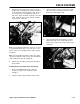
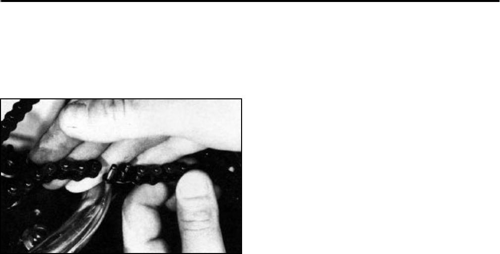
13. Place the chain around both sprockets (Figure
121). Install the master connecting link. When
reinstalling the locking clip, slide the clip over one
end of the master connecting link, and with the
use of a needle nose pliers, lift the other end of the
locking clip in place.
Figure 121 0217-072
14. Pull the engine back until the chain is snug, with
no more than 1/8 inch deflection or slack (Figure
107).
15. Retighten the four bolts in sequence as illustrated
in the Chain Adjustment Procedure (Figure 108).
Torque to 170 - 220 in·lbs. Then tighten the
starter housing bolt, on the recoil starter housing,
70 - 120 in·lbs (Figure 106).
16. Replace the shrouding, chain guard, and spark
plug lead wire.
Impeller Sprocket/Tube Assembly And Bushing
Replacement (1965 - 1971) 14” And 21” Models
As discussed in the "Chain Adjustment Procedure (all
models)" on page 5 - 20, the proper chain tension is
critical to the impeller sprocket service life. The correct
chain tension, when properly maintained, will also
increase the life of the rotor shafts and bushings.
Should the impeller sprocket, bushings or rotor shafts
need replacement, proceed with the following:
1. Refer to "Crankshaft Sprocket Replacement (all
models)" on page 5 - 21. Complete steps 1 and 2.
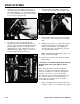
2. Using a needle nose pliers, remove the locking
clip on the master connecting link of the chain
(Figure 109). Remove master link and remove the
chain.
3. After removing the chain, remove the four bolts,
two on the left side and two on the right side of the
impeller housing, retaining the paddles, impeller
sprocket, bushings, and rotor shafts (Figure 116).
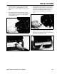
4. Remove the entire impeller assembly from the
snowthrower (Figure 117).
Note: If your unit is equipped with a stripper
assembly, remove the two self-tapping screws,
and remove from the housing (Figure 114 and
Figure 115).
5. Remove both rotor shafts from each end of the
sprocket and tube assembly (Figure 119). Inspect
shafts, bushings, and sprocket.
6. Remove all screws retaining paddles to sprocket/
tube assembly (Figure 119). (Note position of
reinforcing strap over paddles.)
7. Replace with a new sprocket/tube assembly. It is
a good idea to also replace the bushings and rotor
shafts at this time. Replace paddles if needed.
8. Slide new sprocket/tube assembly back into
housing of snowthrower and align the rotor shafts
with the four mounting holes. Tighten the four
bolts (Figure 116).
9. Reinstall stripper assembly, if your unit is so
equipped. Some stripper assemblies have slotted
holes on the housing for the stripper to be
adjusted.
Rotate the paddles to assure proper clearance.
Should the stripper show wear, replace.
10. Refer to "L.H. And R.H. (Left Hand And Right
Hand) End Cap/Bushing Replacement (1972-
1980) 14” And 21” Models" on page 5 - 22.
Complete steps 13 through 16.
Chain Replacement
Design of the 14” and 21” snowthrowers, like any
mechanical product, is a compromise between
durability, performance, and cost. After a period of
time, moving parts, like the chain on your 14” and 21”
snowthrower, are expected to wear out. This can be
due to environmental effects, unusual use, irregular
maintenance, and other causes.