STX 165 / STX 165R Installation Manual 3700 Osuna Rd NE, Suite 711 Albuquerque, NM 87109 www.sandia.
This document and the information contained herein is the proprietary data of SANDIA aerospace Corporation. No part of this document may be transmitted, reproduced, or copied in any form or by any means without the prior written consent of SANDIA aerospace. Due to SANDIA aerospace’s continued product and quality improvement programs, information contained in this document is subject to change without prior notice Copyright 2010 SANDIA aerospace Corporation, All right rights reserved.
Table of Contents Record of Revisions.....................................................................................................................................1 Table of Contents........................................................................................................................................2 List of Illustrations......................................................................................................................................
3.6.3 3.6.4 3.7 3.7.1 3.7.2 3.8 3.9 3.9.1 3.9.2 3.9.3 3.9.4 3.9.5 3.10 3.10.1 3.10.2 3.10.3 3.10.4 3.10.5 3.10.6 3.10.7 3.10.8 3.11 3.11.1 3.11.2 Outside Air Temp Probe................................................................................................14 Antenna Connector.......................................................................................................14 Connector Pin Out........................................................................................................
Section 1 General Description 1.1 Introduction This manual describes the installation of the SANDIA aerospace STX 165 and STX 165 Mode C transponders. It is intended for use by FAA certified repair stations to install the STX 165 and STX 165R transponders and includes both mechanical and electrical installation information. Calibration, system configuration and checkout procedures are included.
1.3.3 1.3.3.1 Operational Characteristics STX 165 Panel Mount Operational Voltage: 11-32Vdc Current: All Current readings are with the encoder heater on Aircraft Power 14Vdc 14Vdc 28Vdc 28Vdc 1.3.3.2 PRF 500 500 Squawk Code 7777 1200 Watts 13.16 11.49 Current .94A .82A 500 500 7777 21.14 .76A 1200 19.68 .
Environmental Qualification Form for the STX 165 Mode C Transponder NOMENCLATURE: TYPE/MODEL/PART No.
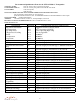
Environmental Qualification Form for the STX 165R Mode C Transponder NOMENCLATURE: STX 165R, Airborne ATC Transponder Equipment TYPE/MODEL/PART No.
2.1 Section 2 Installation Considerations GENERAL The STX 165 is self contained panel mounted Mode C transponder with a built-in encoder. In addition to providing Mode C altitude for it’s internal use, the STX 165 outputs the encoders pressure altitude in an RS 232 format for use with other on board systems that require pressure altitude information. The baud rate for the RS 232 output is selected (9600 or 1200 baud) in the installer setup mode during installation.
3.1 Section 3 Installation Procedures General The STX 165 and STX 165R are supplied with two Sub-D mating connectors and a connector clamps. The Sub-D connectors use screw lock assemblies to secure the connectors to the unit. In some installations both connectors will not be needed. The spare connector can be discarded. Also supplied is a SMA connector for use in connecting the antenna coax.
3.3 Electrical The STX 165 and STX 165R operate on 11-32Vdc. Power should be protected by a 1 amp fuse or circuit breaker. J3, a 9 pin Sub-D connector, has system power, external Ident and RS 232 altitude functions. J2 is a 15 pin Sub-D connector that has the Gilham Gray code and OAT functions. On the STX 165 panel mount unit, the gray code connections are outputs on J2 and on the STX 165R remote unit the gray code connections are inputs.
Figure 3-2 STX 165 Top View Dimensions 3.4.2 STX 165R The STX 165R remote transponder can be either hard mounted using the mounting flanges or mounted in the optional mounting tray. 3.4.2.1 Mounting Tray When using the mounting tray, it needs to be secured with two number 8 pan head mounting screws. Ensure that the top of the screw head is below the mounting tray surface. The STX 165R can be installed in either direction in the mounting tray.
3.4.2.2 Hard Mounting without Tray The STX 165R can be hard mounted to the aircraft using the slotted flanges on the unit using either number 6 or number 8 mounting screws. It can be mounted in either axis. When mounted on the narrow edge two screws are used to fasten the unit. When on the wide edge, either three or four mounting screws are required. When mounting the unit, ensure that enough clearance is allowed for the mating connectors.
3.5 3.6 3.6.1 3.6.2 Static Port Connection The STX 165 has a built-in altitude encoder that requires connection to the aircraft static port. The static port connection is on the back of the STX 165. To ensure a leak proof fit, it is recommended to use tubing with an Inside Diameter of .125” and secure it with a hose clap or ty-wrap. Upon completion of the STX 165 installation a leak test of the static line is to be performed per FAR Part 43 Appendix E.
3.6.3 Outside Air Temperature (OAT) Probe Installation Avoid mounting the OAT probe in or near prop airstream, engine or heater exhaust, transmitting antennas or on dark painted surface. Failure to do so will result in improper OAT readings. The OAT probe requires a 7/16” hole be drilled in the skin of the aircraft. The installer should consider fabricating an appropriate doubler plate in accordance with accepted installation practices as outlined in AC 43.13-1B.
Figure 3-9 Antenna SMA Assembly 1. Strip cable to dimensions shown. Do not nick braid or center conductor. 2. Solder contact to center conductor. 3. Flare braid and slide body assembly over contact and under braid. Then seat body assembly firmly onto contact. The cable may have to be held in a clamping fixture. Arrange braid uniformly around crimp stem. Slide crimp sleeve forward and crimp using recommended crimp tool. Slide heat shrink froward and shrink ( as applicable.
3.7 3.7.1 Connector Pin Out STX 165 Panel Mounted Unit Pin # 1 2 3 4 5 6 7 8 9 Description Aircraft Power 11-33Vdc RS 232A (TCMD) Serial Ground RS232B (Altitude In) Aircraft Ground External Ident RS232A (TSTAT) RS232B (Altitude Out) I/O In In In In In In Out Out Supression In Notes 9600 Baud 9600/1200 Baud Selectable. 9600 Baud Factory Default <.5V= Low, >1.
3.7.2 STX 165R Remote Mounted Unit Pin # 1 2 3 4 5 6 7 8 9 Description Aircraft Power 11-33Vdc RS 232A (TCMD) Serial Ground RS232B (Altitude In) Aircraft Ground No C RS232A (TSTAT) RS232B (Altitude Out) I/O In In In In In Out Out Suppression In Notes 9600 Baud 9600/1200 Baud Selectable. 9600 Baud Factory Default <.5V= Low, >1.
3.8 Calibration Procedures - STX 165 Panel Mount Unit NOTE: The Primary Flight Altimeter must be calibrated per Part 43 Section E. Verify compliance with AC-43.13 as applicable. 1. 2. 3. 4. 5. 6. 7. 8. 9. 10. 11. 3.9 3.9.1 Connect the pitot-static test set to the aircraft static system. The STX 165 must be connected to the aircraft static line. Apply power to the STX 165 and allow the internal encoder to stabilize.
3.9.2 OAT Correction The OAT probe should not generally require any calibration. However, in the event that the component in the OAT probe age after several years, OAT temperature can be trimmed. To trim the OAT setting ensure that the OAT probe sensor is at a known temperature, such as 32o F 1. Rotate the Data knob to select OAT Correction page 2. Press the Enter pushbutton. The brackets will extinguish and the Offset temperature will begin blinking 3.
3.10.2 TEMPERATURE UNIT If the optional OAT probe is installed, this page changes the Temperature display to the pilot between Fahrenheit and Celsius. All Temperature functions will be set to the selected unit. 1 Rotate the Data knob unit the Temperature Unit page is displayed. 2. Rotate the Select knob counter clockwise to select Celsius and clockwise to select Fahrenheit. 3.10.
3.10.7 DEFAULT VFR CODE The factory default VFR code is set to 1200, the normal US VFR code. The pilot can change the VFR code to the one used in his local area. 1. Rotate the Data knob to select DEFAULT VFR 2. Press the Enter pushbutton. The brackets will extinguish and the first digit in the squawk code will blink, indicating it is ready for programming. 3. Rotate the Data knob to select the desired digit. 4.