
Zero Turn Riding Mower Operator's Manual


10
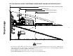
DRIVE HANDLES
The drive handles (left and right) are located at the top of the control tower. (See Figure 8) The drive handles are
used to move, steer, and stop the Z-series. The drive handles will return toward the neutral position when
released; however, the driver should place the drive handles in the neutral position so the unit will not move. If the
drive handles are not placed in the neutral position, the Z-Series may creep.
When the engine is running, the unit will move in accordance with the drive handles (push, pull or both) as they
are moved from the neutral position. When the drive handles are released, they immediately return towards the
neutral position as the unit slows to a stop position (while the engine continues to run).
The rear wheels move and steer the unit. The left drive handle controls the left rear wheel and the right drive
handle controls the right rear wheel. When a drive handle is moved forward, the respective wheel turns forward.
When a drive handle is moved backward, the respective wheel turns in reverse.
Each drive handle has a range in the forward position (push) and the reverse position (pull). If a drive handle is
moved to the full position (until it stops) the rear wheel turns as fast as the throttle is set. Positions between
neutral and full are proportional across the range based on the throttle setting. The drive handles can be moved
together in the same direction or independent of each other in any combination (i.e. left push, right pull). Refer
also to the Quick Reference Chart located in the OPERATION Section.
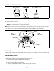
Figure 9
SPEED CONTROL BAR
The speed control bar is connected to the console with two wing nuts. (See Figure 9). It is used as a grab bar for
entry or exit from the tractor and allows for pre-set maximum travel speed.
• Loosen the two wing nuts located on either side of the plastic console.
• Rotate speed control bar to desire location.
• Tighten wing nut to secure speed control bar.
NOTE: Limit loosening the wing nuts to 1 1/2 turns. This will insure proper assembly of the screw not visible on
the other side of the plastic console. Refer to parts book if screw falls and wing nuts are no longer tightening.
The speed control bar also aids the drive handles in making “perfect U-turns”. Grasp both drive handles and the
speed control bar at the same time to move forward, release the left drive handle to turn left and then regrasp to
continue straight ahead or release the right drive handle to turn right. Refer also to the Quick Reference Chart
located in the OPERATION Section.
Wing Nut
Speed Control
Bar