OPERATOR’S MANUAL ZERO TURN TRACTOR Model Numbers ZT 42 w/42" Mower Deck ZT 50 w/50" Mower Deck IMPORTANT: READ SAFETY RULES AND INSTRUCTIONS CAREFULLY Warning: This unit is equipped with an internal combustion engine and should not be used on or near any unimproved forestcovered, brush-covered or grass-covered land unless the engine’s exhaust system is equipped with a spark arrester meeting applicable local or state laws (if any).
TABLE OF CONTENTS TRACTOR PREPARATION .................................................................................................... 2 IMPORTANT SAFE OPERATION PRACTICES ..................................................................... 3 SAFETY DECALS AND LABELS ............................................................................................ 6 RECORDING MODEL AND SERIAL NUMBER INFORMATION ........................................... 8 CUSTOMER SUPPORT ...................................
WARNING • • • The engine exhaust, some of its constituents, and certain vehicle components contain or emit chemicals known to the State of California to cause cancer, birth defects or other reproductive harm. This unit is equipped with an internal combustion engine and should not be used on or near any unimproved forest-covered, brush-covered, or grass-covered land unless the engine’s exhaust system is equipped with a spark arrester meeting applicable local or state laws (if any).
DO: 13. Mow only in daylight or good artificial light. 14. Do not operate the machine while under the influence of alcohol or drugs. Mow across slopes, not up and down. Remove obstacles such as rocks, limbs, etc. 15. Watch for traffic when operating near or crossing roadways. Watch for holes, ruts or bumps. Uneven terrain could overturn the machine. Tall grass can hide obstacles. 16. Use extra care when loading or unloading the machine into a trailer or truck.
8. After striking a foreign object, stop the engine, remove the wire from the spark plug and thoroughly inspect the mower for any damage. Repair the damage before restarting and operating the mower. 5. Never allow children under 14 years old to operate the machine. Children 14 years and over should only operate the machine under close parental supervision and proper instruction. 6.
SAFETY DECALS AND LABELS Keep product safety graphics (decals) clean. Replace any safety graphic that is damaged, destroyed, missing, painted over or can no longer be read. Replacement safety graphics are available through your dealer. START FORWARD REVERSE NEUTRAL STARTING INSTRUCTIONS • • • • • To START, PARK BRAKE must be set. P.T.O. switch in OFF (down) position. Lap bars in NEUTRAL and outward positions. Throttle set properly, CHOKE position if "cold".
SAFETY DECALS AND LABELS TO R ED U CE TH E R IS K O F IN JU R Y, D O N O T O PER ATE U N L ES S D IS CH AR G E CO VER O R GRASS CATCH ER IS IN ITS PR O PER PL ACE. IF D A M A G E D , R E P L A C E IM M E D IA T E L Y . WARNING AVOID SERIOUS INJURY OR DEATH • • • • • • • • • • • • • Read The Operator's Manual. Go Across Slopes, Not Up And Down. If Machine Stops Going Uphill, Stop Blade And Back Down Slowly. Avoid Sudden Turns. Do Not Mow When Children Or Others Are Around.
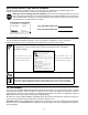
RECORDING MODEL AND SERIAL NUMBER This Operator’s Manual is an important part of your new lawn tractor. It will help you assemble, prepare and maintain the unit for best performance. Please read and understand what it says. Before you start assembling your new equipment, please locate the model plate under the seat of the tractor and copy the information in the space provided below. A sample model plate is also given below.
ZT42SECTION 1: CONTROLS AND FEATURES B O P C A C N M D E L F F G K H J Figure 1 A. B. C. D. E. F. G. H. Deck Height Index Deck Lift Handle RH and LH Drive Control Levers Ignition Switch PTO Switch Transmission Bypass Rod (Not Shown) Cup Holder Storage Tray J. K. L. M. N. O. P. 9 Seat Adjustment Knobs (Not Shown) Fuel Tank Cap Hour Meter /Indicator Panel Throttle Control Choke Control—Model ZT50 ONLY Parking Brake Engagement Lever Trans.
NOTE: References to LEFT, RIGHT, FRONT, and START- The starter motor will turn over the engine. Release the key immediately when the engine starts REAR indicate that position on the tractor when facing forward while seated in the operator’s seat. NOTE: To prevent accidental starting and/or battery discharge, remove the key from the ignition switch when the tractor is not in use. A. Deck Height Index The deck height index consists of six index notches located on the front/right of the seat box frame.
• J. Seat Adjustment Knobs (Not Shown) The seat adjustment knobs are located underneath the seat hinge bracket. The knobs allow for tool free adjustment of the fore to aft position of the operator’s seat. Refer to SECTION 3: ADJUSTMENTS for instructions on adjusting the seat position. Indicator Panel Feature Battery Indicator (Refer to Figure 4) • Illuminates and the battery voltage is displayed briefly when the ignition switch it turned to the "ON" position. K.
• M. Throttle Control The throttle control is located on the LH console to the left of the operator’s seat. When set in a given position, a uniform engine speed will be maintained. ZT42 This symbol indicates the fast position. N. Choke Control - Model ZT50 ONLY The choke knob controls the position of the engine choke. Pull the knob out to choke the engine; push the knob in to open the choke. This symbol indicates the slow position. This symbol indicates the choke position. O.
SECTION 2: OPERATION GENERAL SAFETY BEFORE OPERATING YOUR TRACTOR • • Before you operate the tractor, study this manual carefully. It has been prepared to help you operate and maintain your tractor efficiently. • Familiarize yourself with the operations of all the instruments and controls. • This engine is certified to operate on unleaded gasoline. For best results, fill the fuel tank with only clean, fresh, unleaded gasoline with a pump sticker octane rating of 85 or higher.
• The safety interlock system will shut off the engine if the operator leaves the seat with the PTO engaged, regardless of whether the parking brake is engaged. NOTE: The PTO switch must be moved to the “OFF” position to restart the engine. • The safety interlock system will shut off the PTO and the mower blades will stop if both drive control levers are moved into the reverse position. The PTO will re-engage when one or both of the levers are moved back to the neutral or forward position.
COLD WEATHER STARTING Be sure to use the proper oil for the expected temperatures (check the table in the engine manual). Follow the normal engine starting instructions above. However, allow the engine ample time to warm up before putting the tractor under load. NOTE: Always remove the key from the ignition switch to prevent accidental starting or battery discharge if the equipment is left unattended.
DRIVING FORWARD Control Lever Moved Inward and in Neutral Faster Slower Neutral Position Figure 7 Figure 8 • Move the throttle control lever forward to the full throttle position (3500-3600 RPM). NOTE: The tractor and engine are designed to run at full throttle. If performing a practice session, it is preferable that the tractor is operated at less than full throttle (approximately 2500-3000 RPM), but this only applies to practice operation.
IMPORTANT: Always maintain your grasp on the drive control levers. Do not release the levers to slow the tractor or to return to neutral. - To turn to the right, move the right drive control lever rearward of the left lever. See Figure 10. FORWARD RIGHT TURN Turning While Driving Rearward • To turn the tractor while driving rearward, move the control levers as necessary so that one lever is forward of the other. The tractor will turn in the direction of the forward control lever.
STOPPING THE TRACTOR • Move both drive control levers to the neutral position to stop the motion of the tractor. • Push the PTO switch downward to the disengaged position. • Use the deck lift handle to raise the deck to its highest position. • If dismounting the tractor: - Move the drive control handles fully outward in the neutral position. - Engage the parking brake. - Move the throttle control lever to the fast position if operating a ZT42 tractor, or to the slow position if operating a ZT50 tractor.
• Place the shift lever in neutral, • Engage the parking brake, • Shut engine off and remove the key. Doing so will minimize the possibility of having your lawn ‘‘browned’’ by hot exhaust from your tractor’s running engine. USING THE MOWER DECK WARNING: Make certain the area to be mowed is free of debris, sticks, stones, wire or other objects that can be thrown by the rotating blades. IMPORTANT: Do not engage the mower deck when lowered in grass.
SECTION 3: ADJUSTMENTS ADJUSTING THE OPERATORS SEAT • Remove the two hex insert lock nuts from the hex cap screws securing the control lever to the control pivot bracket. Refer to Figure 17. • While holding the hex cap screws in the control lever mounting bracket, remove the control lever w/screws from the pivot bracket and reposition by inserting the screws into the other pair of holes. • Secure the control lever with the two hex insert lock nuts.
SECTION 4: MAINTENANCE • ENGINE MAINTENANCE Engine maintenance procedures and schedules can be found in the engine manual. Follow those instructions for performing engine maintenance. • If needed, use a quality 20W50 motor oil and add only enough oil to bring the level within 1/4" of the bottom of the reservoir. Reinstall the cap and fully tighten. Using the Engine Oil Drain Valve • Locate the oil drain valve on the left side of the engine.
• BATTERY REMOVAL WARNING: Battery posts, terminals and related accessories contain lead and lead compounds. Wash hands after handling. • Always keep the battery cables and terminals clean and free of corrosion. Avoid tipping. Even a sealed battery will leak electrolyte when tipped. BATTERY STORAGE • When storing the tractor for extended periods, disconnect the negative battery cable. It is not necessary to remove the battery. • All batteries discharge during storage.
TRACTOR CREEPING Creeping is the slight forward or backward movement of the tractor when the engine is running at high idle and the drive control levers are opened out in the neutral position. If after operating the tractor for some time, it begins to creep while in the neutral position, adjust the transmission control rods as follows. • Place the front of the tractor against an immovable object (e.g. wall, post, etc.).
TRANSMISSION DRIVE BELT If the transmission drive belt becomes worn and causes the drive transmissions to slip, the drive belt must be replaced. To replace the drive belt, proceed as follows: • Remove the deck drive belt from the PTO clutch on the bottom of the engine following the instructions in Deck Removal, SECTION 5: MOWER DECK. • From beneath the rear of the tractor, insert a 3/8 inch drive ratchet into the square hole of the drive idler bracket. See Figure 24.
• Fill the fuel tank with treated fuel and run the engine for 2-3 minutes to get stabilized fuel into the carburetor. TRACTOR STORAGE If your tractor is not going to be operated for an extended period of time (thirty days to approximately six months), the tractor should be prepared for storage. Store the tractor in a dry and protected location. If stored outside, cover the tractor (including the tires) to protect it from the elements.
SECTION 5: MOWER DECK This section contains removal, installation, adjustment, and maintenance information for the 42-inch (ZT42) and 50-inch (ZT50) mower decks. 42 INCH DECK SHOWN Rear Deck Hanger Bracket DECK REMOVAL Deck Lift Arm Remove the mower deck from the tractor as follows: • Move the tractor to a level surface, disengage the PTO, stop the engine, and set the parking brake. • Move the deck gauge wheels to their highest setting (lowest deck setting).
• • • • • • • - The deck is properly leveled when both blade tip measurements taken earlier are equal. Use the deck lift handle of the tractor to lower the deck lift arms into the slots of the rear deck hanger brackets. Pull the deck support pins outward and maneuver the deck as necessary to align the holes in the deck lift arm with the pins. Refer to Figure 26. When aligned, push each pin fully inward through the lift arms to secure the arms in the rear hanger bracket slots.
• Front to Back Leveling. The front of the deck should be approximately 1/8 to 1/4 inch lower than the rear of the deck. Adjust if necessary as follows: • If the side to side leveling was done correctly, measuring just the right blade should be acceptable to attain the correct back to front pitch of the deck. • Measure the distance from the front tip of the blade to the ground and the distance from the rear tip to the ground. The front distance should be 1/8 to 1/4 inch less than the rear.
• Insert the shoulder screw in the one of four index holes that will give the gauge wheel a 1/4 to 1/2 inch clearance with the ground. • Note the index hole of the just adjusted wheel, and adjust the other gauge wheels into the respective index holes on the other gauge wheel brackets on the deck. • Use a 15/16 inch wrench to hold the hex nut on top of the spindle assembly when loosening the hex nut securing the blade.
REPLACING THE DECK DRIVE BELT • Remove the deck from beneath the tractor, (refer to Deck Removal on page 26). • Remove the hex tapping screws securing the belt covers to the deck and remove the belt from the spindle pulleys. Refer to Figure 33. • Depending on which deck (42" or 50") you are working on, install the new belt around the spindle pulleys as shown in the applicable graphic of Figure 33. Reinstall the belt covers.
NE, R WARNING 15° N DO TTE D LI EPR ES ENT ING A 15 ° SL OPE Do not mow on inclines with a slope in excess of 15 degrees (a rise of approximately 2-1/2 feet every 10 feet). A riding mower could overturn and cause serious injury. If operating a walk-behind mower on such a slope, it is extremely difficult to maintain your footing and you could slip, resulting in serious injury. Operate RIDING mowers up and down slopes, never across the face of slopes.
NOTES 54
NOTES 55