Hydrostatic Zero-Turn Residential Riding Mower Turf Equipment MODEL 20HP Z-Force 44 23HP Z-Force 50 Model Shown is a 23HP Z-Force 50 OPERATOR’S AND SERVICE MANUAL
TABLE OF CONTENTS Foreword. . . . . . . . . . . . . . . . . . . . . . . . . . . . . . . . . . . . . . . . . . . . . . . . . . . . . . . . . . . . . . . 3 General Safety Operations . . . . . . . . . . . . . . . . . . . . . . . . . . . . . . . . . . . . . . . . . . . . . . . . . 4 A. General Operation . . . . . . . . . . . . . . . . . . . . . . . . . . . . . . . . . . . . . . . . . . . . . . . . . 4 B. Slope Operation . . . . . . . . . . . . . . . . . . . . . . . . . . . . . . . . . . . . . . . . . . . . . .
FORWARD The Hydrostatic Zero-Turn Riding Mower provides superb maneuverability and mid-mount cutting. The machine incorporates many safety features that should be studied by all operators before use. The list of safety precautions should receive particular attention. This manual presents all of the operating and maintenance instructions necessary to keep your mower at peak efficiency. If operated and maintained properly, your mower will give dependable service.
WARNING • • • The engine exhaust, some of its constituents, and certain vehicle components contain or emit chemicals known to the State of California to cause cancer, birth defects or other reproductive harm. This unit is equipped with an internal combustion engine and should not be used on or near any unimproved forest-covered, brush-covered, or grass-covered land unless the engine’s exhaust system is equipped with a spark arrester meeting applicable local or state laws (if any).
17. 18. 19. 20. 21. 22. 23. • Remove obstacles such as rocks, limbs, etc. • Watch for holes, ruts or bumps. Uneven terrain could overturn the machine. Tall grass can hide obstacles. • Use slow speed. Choose a low enough speed so that you will not have to stop while on the slope. • Follow the manufacture’s recommendations for counterweights with attachments to improve stability. • Use extra care with grass catchers or other attachments. These can change the stability of the machine.
. 7. Use extra care when approaching blind corners, shrubs, trees or other objects that may obscure your vision of a child or other hazard. Remove the key when the machine is left unattended to prevent unauthorized operation. 10. D. SERVICE 1. Use extreme care in handling gasoline and other fuels. They are extremely flammable and the vapors are explosive. a. Use only an approved container. b. Never remove fuel cap or add fuel with the engine running.
G. Towing cases should not be punctured. Lead is poisonous and is contained within the positive and negative terminals as well as within the battery’s internal gridwork of plates and active materials. 1. Tow only with a machine that has an approved hitch designed for towing. Do not attach towed equipment except at the hitch point. 2. Follow the manufacturers recommendation for weight limits for towed equipment and towing on slopes. 3. Never allow children or others in or on towed equipment. 4.
SAFETY DECALS AND LABELS Belt Routing Part Number: 777I22757 Part Number: 777I22444 (for 50” Deck) Part Number: 777I22215 (for 60” Deck) TO REDUCE THE RISK OF INJURY, D O N OT O P E RAT E M OW E R U NL E S S DISCHARGE CHUTE COVERORGRASS C A T C H E R IS I N I T S P R O P E R P L A C E .
SPECIFICATIONS Engine: Type: Air Cleaner: Lube System: Starter: Traction Drive: 20HP Kohler Courage Pro (44”) & 23HP Kohler Courage Pro (50”) Vertical air cooled V-Twin Paper element Pressurized with oil filter, drain valve with hose 12-volt electric Engine to variable-speed integrated hydraulic pump and wheel motors on each drive wheel Cutter Deck;Drive: 44” & 50” belt driven Clutch: Electric Deck Lift: Foot Pedal with pin lock for height adjustment at 1/4” increments Cutting Height: 1" to 4" No.
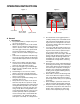
OPERATING INSTRUCTIONS Figure. 1 Figure. 2 parking brake Hour Meter Electric Blade Clutch Switch Ignition Switch Choke A. General k. Engine throttle Be careful when crossing gravel paths or roadways. Always turn off the blade clutch switch and wait until the blades stop rotating and raise the cutting deck to the transport position. Always allow other vehicles to have the right of way. l.
next and each subsequent time that the area is mowed. 2. Safety Awareness when Mowing a. Do not operate on steep slopes, those above 15 degrees (27% slope). b. Avoid turning downhill if possible, use extra care and go slowly. c. Avoid turning when going downhill, traction is at a minimum going downhill. d. Do not operate with discharge side of the mower toward streets, buildings, playgrounds, parking lots, other machines, animals, and other people. e.
Steering Levers Figure. 4 Figure. 3 Fuel Shutoff Valve 8. Seat Adjustment Lever: The Seat Adjustment Lever is located beneath the seat. The Seat Adjustment Lever is used to move the seat forward and backward. To place the seat in the desired position pull the seat adjustment lever to the left then push the seat forward or back to the desired position. Release the lever so the seat will lock in place. 9. Hour Meter: (See Figure 1) Located on the right side of the mower behind the ignition switch.
C. Initial Adjustments 1. Check the fluid levels and tires: plugs and using the foot pedal, lower the mowing deck into the cutting position. Using a ruler, pencil and paper, measure and note the distance from the paved surface to the bottom edge of the mowing blade at the front and the back of the deck on each side of the mower. (Four dimensions.) b. Note: These checks should be made daily, before starting the engine. a.
5. Lubricate all fittings listed in the maintenance section. 1. Make sure the park brake is set to the “ON” position, both lap bars are in the neutral/start position, and the Power Take Off (PTO also referred to as blade control switch) is in the “off” (down) position. 2. Move the choke to the “on” (up) and the engine speed control (throttle) forward to the end of the slot. 3.
toward the opposite from the side that was advanced — I.E. to turn clockwise (to the Right), move the LEFT lap bar forward more than the right side, and to turn counter-clockwise (to the LEFT), move the RIGHT lap bar forward more than the left side. NOTE: If one lap bar is in the neutral position and the other is advanced, the turn side tire will not rotate and a “pivot turn” will be executed — turf defacement could occur (if on grass) as well as potential damages to the traction surface and the tire.
e. Push the throttle control to the full forward position. f. Insert the key in the ignition and start switch and turn the switch to “On”. g. Gasoline Engine: If the engine is cold, pull the choke to the “on” (up) position. h. Turn the ignition key in a clockwise direction to the “Start” position until the engine starts. j. k. Note: Do not hold the key in the “Start” position for more than 10 seconds or you may damage the starter.
Trailing Link hair pin hair pins Figure. 6 B.Mower Deck e. Thread hose coupler (packaged with this manual) onto the end of your garden hose. See Figure 7. f. Attach the hose coupler to the water port on your mower deck’s surface. See Figure 7. Turn the water on. g. While sitting in the machine operator’s position, re-start the engine and place throttle lever in the Fast (rabbit) position. h. Move the PTO control to the “ON” position. i.
g. To replace the blade reverse the above process and tighten nut to 100-120 lb ft. Note: Add a small amount of multi-purpose grease to the bolt threads to avoid corrosion and galvenic action. Spindle WARNING: Never mow with dull blades! Blades that are bent should be replaced! The cutting blades are sharp and can cause severe injury. Wrap the cutting surface of the blade with a rag to avoid injury. 3. Sharpening the Blade: a. Set the parking brake. b. Clean any debris from the blades.
D.Electrical Circuit 4. Installing the Battery Note: The battery is delivered from the fac- Danger: tory fully charged and filled with electrolyte. a. Attach the positive (red) cable. b. Attach the negative (black) cable. c. Attach the rubber battery strap. 5. Jump Starting Read General Safety Precautions Nos. 9 and 10. 1. Battery: The battery is located beneath the operator’s seat.
should rotate. If the blades do not turn, the blade clutch switch must be replaced, the seat switch must be replaced or the electric PTO clutch must be repaired. mount from the operator’s seat, the seat switch must be replaced. d. Electric PTO Clutch: This clutch operates when the engine is running, the operator is in the operator’s seat and the blade clutch switch is turned on. This electric clutch is a fairly trouble free device.
the wheel. Mount a wheel and tire, replace the lug nuts, and using a torque wrench, tighten them to 60 ± 10 ft-lbs. rear and lower the wide area of the rod into the keyhole slot. (See photo below). If the leaking tire is on a front caster wheel, block both traction wheels and raise the caster wheel so that the tire is an inch off the ground. Loosen and remove the locknut from the axle assembly and pull the axle assembly from the caster yoke. The wheel and two spacer sleeves will drop free.
neutral position. If the mower begins to creep, contact your service representative. d. Lower the mower off the block and check the tire pressure. e. Push the mower outdoors and start the engine. Let the engine idle until it has warmed up completely (4 to 5 minutes). H. Storage 1. General: If your mower will not be in service for a few months, it should be stored in a dry location that is not subject to drastic changes in temperature.
MAINTENANCE SCHEDULE 6. A. Daily Checks D. Every 100 Hour Checks 1. Before starting engine: a. Check the fuel level by viewing in the tank. b. Check the engine oil level.** c. Check the hydraulic transaxles for leaks. d. Check the tires and tire pressure. Drive Tires: 8-10 psi. Front Caster Wheels: 20-25 psi. e. Check the spindle belt, the mower drive belt and the hydro drive belt. f. Check the blades. Make sure they are sharp and that the blade securing cap screws are tight. g.
. OIL CHART Apply a few drops of SAE engine oil, grease, or use a spray lubricant. Apply the oil to both sides of pivot points. Wipe off any excess. Start engine and operate mower briefly to insure that oil spreads evenly.
Performance Adjustments B. Engine RPM Check and Adjustment Table 1 A. High Speed Tracking Adjustment If mower tracks to one side with both lap bars in fully forward position: Check air pressure in all four tires: a. Pressure should be within specified ranges and balanced side-to-side. b. Rear tires 8-10 psi recommended (20 psi MAX.) c. Front tires 20-25 psi recommended (28 psi MAX. 2.
C. Deck Corner Ball Wheel Roller Settings c. Replace the bolts and nuts, and tighten to 28-34 ft-lbs. 1. If angular adjustments are also required, nuts can be tightened until snug at this point. d. The same adjustments should be made to both sides of the mower. 5. To adjust the front-to-rear angle of the lap bars, a. Loosen the nuts on the lap bar mounting bolts, leaving the bottom one fairly snug. b. The top hole is slotted, allowing the lap bar to pivot on the bottom bolt. c.
the key from the ignition switch, disconnect the spark plug wires and using the lift pedal, position the mowing deck into the 3" height of cut position. (The 3" height of cut position is recommended in order for one to see and obtain a measurement. Any height of cut position is acceptable as long as a proper measurement can be taken.) 2. Check the right and left front tire pressure. Adjust as necessary to 20-25 psi. Tire pressure can affect blade height by as much as a 1/4”. 3.
WIRING DIAGRAM GD: 02002990 28
SLOPE GAUGE TTE A1 5 ° S LOP E OR A FENCE POST A CORNER OF A BUILDING A POWER POLE SIGHT AND HOLD THIS LEVEL WITH A VERTICAL TREE USE THIS PAGE AS A GUIDE TO DETERMINE SLOPES WHERE YOU MAY NOT OPERATE SAFELY. FO L D O N DO D LI N E , REP RE S E NTIN G 15° WARNING Do not mow on inclines with a slope in excess of 15 degrees (a rise of approximately 2-1/2 feet every 10 feet). A riding mower could overturn and cause serious injury.
MAINTENANCE RECORD DATE WORK PERFORMED DATE 30 WORK PERFORMED
31
MANUFACTURER’S LIMITED WARRANTY FOR CUB CADET Z-FORCE ZERO-TURN RIDING MOWER IMPORTANT: To obtain warranty coverage owner may be required present proof of purchase and applicable maintenance records to the servicing dealer. Please see the operator’s manual for information on required maintenance and service intervals. In addition, Cub Cadet may deny warranty coverage if the hour meter, or any part thereof, is altered, modified, disconnected or otherwise tampered with.