
Specifications

6
ATTACH THERMOSTAT TO SUBBASE
IT IS RECOMMENDED THAT YOU SET OPTION
SWITCHES TO DESIRED POSITION BEFORE ATTACH-
ING ON SUBBASE (see OPERATION). IT IS ALSO
RECOMMENDED THAT YOU PROGRAM THE
THERMOSTAT WITH BATTERY INSTALLED BEFORE
ATTACHING ON SUBBASE (see OPERATION GUIDE
for programming instructions).
POWER TO THERMOSTAT MUST BE OFF BEFORE
ATTACHING THERMOSTAT TO WALL. FAILURE TO
TURN OFF POWER BEFORE ATTACHING THERMO-
STAT MAY CAUSE EQUIPMENT DAMAGE DUE TO
RAPID COMPRESSOR CYCLING.
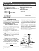
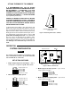
To attach thermostat to subbase, line up the plastic snap
guides at the top of the thermostat and the 4 connector
pins on the thermostat with the connectors near the top
right section of the subbase (when viewed from the front).
Gently pivot the thermostat down until the 9-pin connec-
tors and the plastic snaps lock into place (see fig. 7). Be
gentle when attaching thermostat. If the thermostat
does not seem to be attaching to the subbase easily,
make sure that the connector pins and plastic snaps are
properly aligned, and that excess wire is pushed into the
wall. Damage to the thermostat may occur if force is
used.
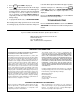
3. Multi-stage (Fossil Fuel) System — up to 3 heat
stages and 2 cool stages
4. Multi-stage (Electric Heat) System — up to 3 heat
stages and 2 cool stages
ENGAGE TWO UPPER GUIDES;
PIVOT DOWN
Figure 7. Attaching thermostat to subbase
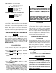
SYSTEM CONFIGURATION
ANY TIME AN OPTION SWITCH IS CHANGED, THE 9
VOLT ENERGIZER
®
BATTERY MUST BE REMOVED
FOR A MINIMUM OF 2 MINUTES.
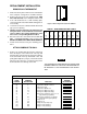
SET OPTION SWITCHES
1. Single Stage Compressor Heat Pump — with re-
versing valve energized through B or O terminals
2. Two Compressor (Split) System
OPERATION
NOTE
ON
1234
Switch #1
Switch #2
Switch #3
Switch #4
(
see step 6
)
OFF
ON
OFF
W1 Y1
Field jumper W1 & Y1
W2 Y2
Field jumper W2 & Y2
ON
1234
Switch #1
Switch #2
Switch #3
Switch #4
(
see step 6
)
ON
OFF
OFF
ON
1234
Switch #1
Switch #2
Switch #3 (see step 5)
Switch #4
(
see step 6
)
ON
ON
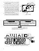
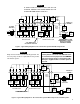
Figure 8. Back of Thermostat
Option Switches 9-pin Connector
4-pin Connector
Battery
W18
ON
1234
Switch #1
Switch #2
Switch #3
Switch #4 (see step 6)
OFF
OFF
OFF
W1 Y1
Field jumper W1 & Y1