
Installation instructions


6
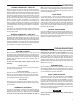
MVH (Pin 1) gas valve SECOND STAGE
PS2 (Pin 2) 2nd stage pressure switch INPUT
FP (Pin 3) flame sensor probe*
GND (Pin 4) MUST BE RELIABLY GROUNDED TO CHASSIS
TH (Pin 5) 24 VAC transformer (low voltage HIGH SIDE)
HLI (Pin 6) high limit INPUT
MVL (Pin 7) gas valve FIRST STAGE
MV COM (Pin 8) gas valve COMMON
TR (Pin 9) 24 VAC transformer (low voltage COMMON SIDE)
GND-2 terminals (Pin 10) MUST BE RELIABLY GROUNDED TO CHASSIS
HLO (Pin 11) high limit OUTPUT
PS1(Pin 12) 1st stage pressure switch INPUT
50V51-843
TERMINAL
TERMINAL
TYPE
SYSTEM COMPONENT
CONNECTION
24 VAC COMMON
low heat speed select OUTPUT Circulator Blower
24 VAC COMMON
Delay tap OUTPUT to circulator
Cool tap OUTPUT to circulator
“YLO” OUTPUT to circulator
adjust tap OUTPUT to circulator
24 VAC COMMON
“O” OUTPUT to circulator
Humidistat/Y-Y2 OUTPUT to Circulator Blower
Heat tap OUTPUT to circulator
24 VAC OUTPUT to circulator
“W2” OUTPUT to circulator
“Y” OUTPUT to circulator
“G”/YLo OUTPUT to Circulator Blower
green CFM indicator
16-pin
connector
& harness
50V51-843 TYPICAL SYSTEM WIRING TABLE
* maximum recommended flame probe wire length is 36 inches.
NOTE: Spade terminals are 0.25” x 0.032”
W1
W2
G
R
B/C
YLO
Y
DEHUM
O
E2-1
E2-2
E2-3
E2-4
E2-5
E2-6
E2-7
E2-8
E2-9
E2-10
E2-2
E2-12
E2-13
E2-14
E2-15
E2-16
9-screw
terminal
block
IGN ( Pin 1) ignitor HOT side
IND HI (Pin 2) inducer HIGH SPEED HOT side
IND LO (Pin 3) inducer LOW SPEED HOT side
IND N (Pin 4) inducer NEUTRAL side
IGN N (Pin 5) ignitor NEUTRAL side
spade terminal
spade terminal
spade terminal
spade terminal
spade terminal
spade terminal
spade terminal
spade terminal
spade terminal
spade terminal
circulator blower HOT terminal
input voltage (120 VAC) HOT side
24 VAC transformer line voltage HOT side
electronic air cleaner HOT side
humidifier HOT side
circulator blower NEUTRAL side
input voltage (120 VAC) NEUTRAL side
24 VAC transformer line voltage NEUTRAL side
humidifier NEUTRAL side
electronic air cleaner NEUTRAL side
CIRC
LINE
XFMR
EAC (optional)
HUM (optional)
CIRC N
LINE N
XFMR N
HUM N (optional)
EAC N (optional)
two-stage thermostat W1 terminal (or equivalent)
two-stage thermostat W2 terminal (or equivalent)
two-stage thermostat G terminal (or equivalent)
two-stage thermostat R terminal (or equivalent)
two-stage thermostat B/C terminal (or equivalent)
two-stage thermostat Y terminal (or equivalent)
two-stage thermostat Y2 terminal (or equivalent)
humidistat enable OUTPUT to circulator
H/P or cooling mode OUTPUT to circulator
MVH
HLO
THPS2
GNDGND
MVL
FP
HLITRPS1
MV
COM
IGN
IND
LO
IND
N
IND
HI
IGN
N
WIRING