
Installation Instructions


4
WIRING CONT.
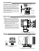
All wiring should be done in accordance with local and national electrical codes and ordinances.
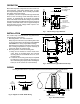
MAKE L2 “HOT”
ON 120V MODELS
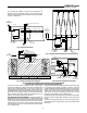
Fig. 9. Typical Wiring Diagram to “Sequence” two or more loads
A
B
A
B
A
B
WIRING
Line Voltage
Line Voltage Field
Low Voltage
L1
L2
LOAD # 1
BLACK
BLUE
YELLOW
BLACK
BLUE
YELLOW
BLACK
BLUE
YELLOW
SILENT
OPERATOR # 1
RED
WHITE
RED
WHITE
RED
WHITE
TO LOW VOLTAGE
ROOM THERMOSTAT
NOTE
Use thermostat with a .2A fixed heater,
or set adjustable heater in thermostat
at .2A.
LOAD # 2
SILENT
OPERATOR # 2
L1
L2
FIELD INSTALLED
WIRE NUT
LOAD # 3
SILENT
OPERATOR # 3
L1
L2
TO YELLOW
LEAD OF
ADDITIONAL
LEVEL TEMPS
Leads “A” and “B” must be alternated between
L1 and L2 as shown for each Silent Operator
used.
CAUTION
W
R
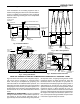
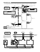
Fig. 10. Typical Wiring Diagram to Operate two or more loads simultaneously
The thermostat circuit current in-
creases 0.2A for each additional
Level-Temp. Thus the heat-antici-
pation should be 0.2A for one
Level-Temp., 0.4A for two, 0.6A
for three, etc. Max number of Level-
Temps. is 5 and thermostat cur-
rent would be 1.0Amps.
LOAD # 1 LOAD # 3LOAD # 2
L1
L2
LINE
SILENT
OPERATOR #1
SILENT
OPERATOR #3
SILENT
OPERATOR #2
BLUE
BLACK
YELLOW
BLUE
BLACK
YELLOW
BLUE
BLACK
YELLOW
TO ADDITIONAL
LOADS AND
LEVEL TEMPS
TO RED & WHITE
LEADS OF
ADDITIONAL
LEVEL TEMPS
RED
WHITE
RED
WHITE
RED
WHITE
HEATING
THERMOSTAT
MAKE L2 “HOT”
ON 120V MODELS