
Installation Instructions


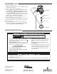

REGULATOR
ADJUSTMENT
TOWER
REGULATOR COVER
SCREW
PLASTIC ADJUST SCREW
REGULATOR SPRING
HOSE BARB
INSTALLED
Figure 5
Figure 6
1. Unplug power cord to the appliance.
2. Slide dryer away from wall.
3. Close manual shut-off valve for dryer, if none present, shut off gas supply line where it enters the building.
A. This appliance does not have a pilot. It is equipped with an
ignition device which automatically lights the burner. Do not
try to light the burner by hand.
B. BEFORE OPERATING smell all around the appliance area
for gas. Be sure to smell next to the floor because some gas
is heavier than air and will settle on the floor.
FOR YOUR SAFETY
“WHAT TO DO IF YOU SMELL GAS”
• Donottrytolightanyappliance.
• Donottouchanyelectricalswitch;donotuseany
phone in your building.
• Immediatelycallyourgassupplierfromaneigh-
bor’s phone. Follow the gas supplier’s instruc-
tions.
• Ifyoucannotreachyourgassupplier,callthe
fire department.
C. Do not use this appliance if any part has been under
water. Immediately call a qualified service technician
to inspect the appliance and to replace any part of
the control system and any gas control which has
been under water.
WARNING
!
If you do not follow these instructions exactly, a fire or explosion
may result causing property damage, personal injury or loss of life.
White-Rodgers is a business
of Emerson Electric Co.
The Emerson logo is a
trademark and service mark
of Emerson Electric Co.
www.white-rodgers.com
www.emersonclimate.com
1. Unplug dryer power cord.
2. Attach a hose and manometer to the hose barb in the tap
of the valve (see figure 5).
3. Turn on system power and energize valve.
4. Remove regulator cover screw and turn regulator adjust
screw clockwise (
) to increase pressure, or coun-
terclockwise (
) to decrease pressure (see figure
6). Always adjust regulator to provide the correct pressure
according to the original equipment manufacturer’s speci-
fications listed on the appliance rating plate.
5. Replace regulator cover screw and tighten securely.
6. Turn off all electrical power to the system.
7. Remove manometer hose from outlet pressure hose barb.
8. Remove hose barb and replace plug. Use pipe sealant.
9. Plug in power cord.
10. Using a leak detection solution, check for leaks at pres-
sure boss screw. Bubbles forming indicate a leak. SHUT
OFF GAS AND FIX ALL LEAKS IMMEDIATELY.
ADJUSTMENT (cont.)
LIGHTING INSTRUCTIONS