
Install Instructions

2
INSTALLATION
The control may be mounted in any location provided that
the temperature and humidity of the air in which it is
located will not cause a condensation on the switch parts.
1. The control should be mounted approximately six feet
from the floor.
2. If the electric conduit goes to a warmer room, put rock
wool around the wires in the conduit where it enters
the control to prevent the flow of warm moist air into
the switch.
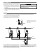
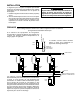
The above diagrams show how a type 2A37 thermostat
can control several steam or hot water unit heaters. Any
number of unit heaters can be operated from one control
provided that the sum of the motor locked rotor currents
or the sum of the full load currents does not exceed the
electrical rating of the thermostat. The Type 11B09 Re-
verse-acting Surface Hot Water Control is used to prevent
operation of the fans when the steam is off or when the
water temperature is too low for proper heating.
TYPE
11B09
TYPE
11B09
TYPE
11B09
SUPPLY
RETURN
TO LINE SWITCH
AND POWER SUPPLY
TYPE
2A37
HOT
N
LINE
ELECTRIC
HEATER
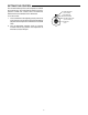
The diagram at left shows how a
2A37 can be used to control an
electric heater.
TYPE
2A37
If the manufacturer of the cooling equipment has supplied
a wiring diagram, follow such recommendations. The
following diagrams show general use of these controls.
All wiring should be done in accordance with local and national electrical codes and ordinances.
WIRING
CAUTION
Do not twist or uncoil the coiled bulb on the top of
the control case. Do not attach conduit through
coiled element to top of control. Instead, run con-
duit to bottom of control.