
Installation instructions


3
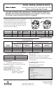
SPECIFICATIONS INSTALLATION
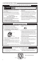
MAIN PIPING CONNECTIONS
NOTE
-
nances, and/or national fuel gas codes.
1. Turn o electrical power to the system at the fuse
box or circuit breaker. Also turn o the main gas
supply.
2. If replacing an existing valve, disconnect all
plumbing and electrical connections from the
old control.
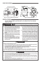
3. The control may be installed in any orientation
(see g. 1). The arrow on
the valve indicates the direction of gas ow
through the control.
4. You should use new pipe that is properly cham-
fered, reamed, and free of burrs and chips. If
you are using old pipe, be sure it is clean and
free of rust, scale, burrs, chips, and old pipe joint
compound.
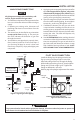
5. Apply pipe joint compound (pipe dope) or teon
tape that is approved for all gases, only to the
male threads of the pipe joints. DO NOT apply
compound or teon tape to the rst two threads
(see g. 3 for typical piping connections).
6. If you are using a vise or open-end wrench to hold
the valve while installing piping, do not tighten
excessively, as this may damage the valve.
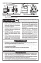
7. If additional clearance for the gas cock knob
is required when installing the new valve in an
existing system, rotate the knob to the position
between ON and OFF. Depress the knob while
turning the valve. The knob will depress only
while in this position.
8. See SYSTEM WIRING when making electrical
connections. After all gas and electrical connec-
tions are completed, turn gas on and check for
gas leaks with leak detection solution or soap
suds. Bubbles forming indicate a leak. SHUT
OFF GAS AND FIX ALL LEAKS IMMEDIATELY.
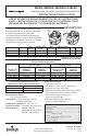
Horizontal
Drop
Piped Gas
Supply
Gas Valve
3 in.
minimum
Gas Valve
Riser
Piped Gas
Supply
3 in.
minimum
Drop
Horizontal
Riser
Gas Valve
Tubing Gas
Supply
3 in.
minimum
NOTE:
Always Include
A Drip Leg In Piping
Figure 1. Typical gas valve piping
Figure 3. Typical gas valve piping
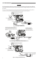
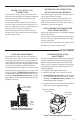
PILOT GAS CONNECTION
Install the tting into the pilot gas outlet (see
g. 4), turning until nger-tight. Insert clean,
deburred tubing all the way through the tting.
While holding the tubing securely, slowly tighten
tting until you feel a slight “give”. Tighten the
tting an additional 1-1/2 turns.
Refer to page 5 for pilot gas adjustment information.
Pilot gas
outlet
Gas outlet
PILOT
PRESS
TAP
Figure 2. Gas valve side view
Figure 4
CAUTION
!
main fuse or circuit breaker box until installation is complete.