
Installation instructions


4
SYSTEM WIRING
NOTE
Always check that the electrical power supply used agrees with the voltage and frequency shown on the
gas control.
The typical wiring diagram shows only the terminal identication and wiring hook up. Always refer to
wiring instructions provided by Equipment Manufacturer for system hookup operation.
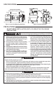
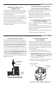
INSTALLATION
ADJUSTMENT
OFF
PILOT
ON
TR
TH
TRTH
PILOT
ADJ.
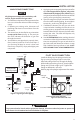
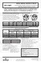
Thermostat
TH, TH-TR to Thermostat
TH-TR, TR to Transformer
Line
24 VAC
Hot
Transformer
Electrical Cut Out (E.C.O.) Switch or
Supplementary Limit in appliance
NOTE: If appliance does not
have E.C.O. Switch
or supplementary limit,
jumper E.C.O. terminals
Figure 5. Wiring for 36C03 (24 VAC)
R
W
Jumper
Power Unit
ECO Terminals (2)
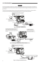
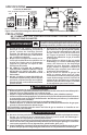
PGTH
TH-
PG
PILOT
ADJ.
Thermostat
Pilot
Generator
TH, TH-PG to Thermostat
TH-PG, PG to Pilot Generator
For appliances without an
Electrical Cut Out (E.C.O.)
device or supplementary high
limit switch, connect black
wire from power unit to TH-PG.
Figure 6. Wiring for 36C03U (750 millivolt Pilot Generator)
PGTH
R
W
For appliances with an Electrical Cut Out (E.C.O.)
device or supplementary high limit switch,
connect black wire from power unit to one side
of the switch. Attach the other side of the switch
to TH-PG.
OFF
PILOT
ON
AD
PILO
Line voltage thermostat
or operating control
High
limit
Line
OFF
PILOT
ON
Electrical Cut Out (E.C.O.) Switch or
Supplementary Limit in appliance
NOTE: If appliance does not
have E.C.O. Switch
or supplementary limit,
jumper E.C.O. terminals
Jumper
Power Unit
ECO Terminals (2)
Figure 5. Wiring for 36C03(24 VAC)
Figure 6. Wiring for 36C03U (750 millivolt Pilot Generator)
Figure 7. Wiring for 36C03A (120 Volt)