
Installation instructions


5
INSTALLATION
ADJUSTMENT
CONNECTION
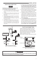
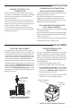
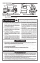
A ve-function valve uses the two E.C.O. termi-
nals that are connected to the magnetic assembly
where the thermocouple connects to the 36C
valve line interrupter.
Connect the leads from the E.C.O. terminals to
the E.C.O. device on the furnace. Test the E.C.O.
device for continuity. If there is no continuity, the
power unit will not hold in. See gure 5.
If the furnace does not have an E.C.O. device,
jumper the E.C.O. terminals on the valve with the
jumper lead provided.
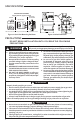
THERMOCOUPLE CONNECTION
24 VAC AND 120
The thermocouple connection should be clean to
ensure good electrical contact.
Run the thermocouple nut into the power unit
tapping as far as possible by hand. Then use a
small wrench to set the nut with a 1/4 to 1/2 ad-
ditional turn. Do not overtighten.
PILOT GENERATOR CONNECTION
.750
Be sure the pilot generator is completely engaged
into the pilot burner.
Be sure that the two terminals from the pilot gen-
erator are securely tightened beneath the proper
screws on the valve.
Connect the power unit lead to the high limit and
the high limit to the TH-PG terminal.
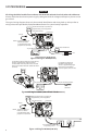
PILOT GAS ADJUSTMENT
If the pilot ame is low and does not engulf the
bulb of the mercury ame sensor, the system will
not energize the main valve. If pilot gas pressure
is too high, gas will sputter past the ignition elec-
trode, and may not ignite. High pilot gas pressure
may also cause the ame to lift o the burner,
causing the ame sensor bulb to sense “low” heat.
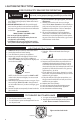
To adjust the pilot gas pressure, remove the cover
screw (see g. 8). To REDUCE pilot pressure, turn
the pilot adjust screw (beneath the cover screw)
clockwise. To INCREASE pilot pressure, turn the
pilot adjust screw counterclockwise. Replace and
tighten cover screw.
Figure 8. Pilot Gas Adjustment
Figure 8. Pilot Gas Adjustment
Pilot adjust
cover screw
Gasket
Pilot
adjust
screw
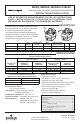
Figure 9. Pressure Regulator Adjustment
Pilot adjust
cover screw
Figure 8. Pressure regulator adjustment
Regulator adjusting
cover screw
OFF
PILOT
ON
PRESSURE REGULATOR
ADJUSTMENT
The pressure regulator has been factory adjusted
(see control label for specic setting). Although
additional adjustments will not normally be nec-
essary, you may adjust the regulator. Do not force
the adjusting screw beyond the limits that it can
easily be adjusted.
1. Energize valve to ignite main burner.
2. Remove“Reg.Adj.”coverscrew(seeg.9).
3. To DECREASE outlet pressure, turn the adjust-
ing screw (beneath the cover screw) counter-
clockwise. To INCREASE outlet pressure, turn
theadjusngscrewclockwise.
4. Replace the cover screw. Cycle the valve two or
threemestoverifyregulatorseng.