
Instructions / Assembly


5
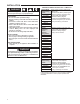
SYSTEM LOCKOUT
& DIAGNOSTIC FEATURES
SYSTEM LOCKOUT FEATURES
When system lockout occurs,
1. Diagnostic LED will flash or glow continuously to indicate
system status.
2. Gas valve is de-energized.
3. Circulator blower is energized at heat speed, and, if
4. Flame is sensed, the inducer blower is energized.
(System lockout will never override the precautionary
features.)
To RESET the control after System Lockout
• Interrupt the call for Heat or Cool at the thermostat for at
least 1 second but less than 20 seconds.
(If flame is sensed with the gas valve de-energized,
interrupting the call for heat at the thermostat will not
reset the control.)
OR
• Interrupt the 24 VAC power at the control for at least 1
second. You may also need to reset the Flame Rollout
Sensor switch.
Serviceable Parts
50M56U-801 has only one serviceable part –an automotive
type fuse, which protects the low voltage transformer from
damage if the output is short-circuited.
• If the fuse has opened up, remove whatever caused
the short circuit and replace the fuse with only a 3 Amp
automotive type fuse.
• If the fuse does not correct the condition, REPLACE
the entire 50M56U-801 control. There are no other user
serviceable parts.
DIAGNOSTIC FEATURES
The 50M56U-801 control continuously monitors its own
operation and the operation of the system.
• If a failure occurs, the LED will indicate a failure code as
shown on page 5 in flash – pause sequences.
• Flash will last approximately for 0.25 seconds, and each
pause will last approximately 2 seconds.
FAULT RECALL
Control must be in STANDBY mode (no call for heat or cool)
• Last 5 fault codes stored can be displayed on the
Diagnostic LED.
• Press the FAULT RECALL switch for approximately 2
seconds or until the LED turns off.
• Release the switch and the LED will remain off for 2
seconds.
• Fault codes will display beginning with the most recent
fault first with a 2 second pause between codes.
• After the stored fault codes have all displayed, the LED
will remain off for 2 seconds and then turn on to indicate
return to normal status.
(While displaying the stored fault codes, the control will
ignore any new call for heat, cool or fan.)
FAULT CODES RESET Automatically after 14
days. To manually reset see steps below.
Control must be in STANDBY switch mode (no call for
heat or cool)
Press the FAULT RECALL switch for approximately 5-10
seconds or until the LED begins to rapid flash.
• Release the switch and the LED will turn off for 2 seconds
indicating that the codes are erased.
• After 2 seconds, the LED will turn on to indicate return
to normal status.
• If the switch is held pressed for over 10 seconds, the rapid
flash will stop and the LED will turn on to indicate return
to normal status and the fault codes will not be erased.
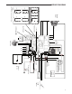
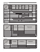
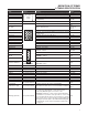
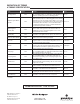
TROUBLESHOOTING
Green
LED
Flash
Amber
LED
Flash
Red
LED
Flash
Error/Condition Comments/Troubleshooting
Below flash codes shall be stored if fault occurs
1 Flame Present Without Gas
Valve Energized
- Verify the gas valve is operating and shutting down
properly.
- Flame in burner assembly should extinguish promptly
at the end of the cycle.
- Check orifices and gas pressure.
2 Pressure Switch Stuck Closed /
Inducer Error
- Check switch function, verify inducer is turning off.
- Refer to wiring diagram, terminals PSI / PSO
3 Pressure Switch Stuck Open /
Inducer Error
- Check pressure switch function and tubing.
- Verify inducer is turning on and pulling sufficient
vacuum to engage switch.
- Refer to wiring diagram, terminals PSI / PSO.
4 High Limit Switch Open - Verify continuity through limit switch circuit.
- Refer to wiring diagram terminals, HLI / HLO.