
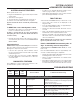
Instructions / Assembly
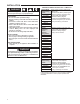

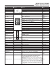


6
Green
LED
Flash
Amber
LED
Flash
Red
LED
Flash
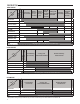
Error/Condition Comments/Troubleshooting
Below flash codes shall NOT be stored
5 Open Flame Rollout Switch
or fuse
- Verify continuity through rollout switch circuit. Refer
to wiring diagram terminals, RO IN / RO OUT.
- Verify continuity of fuse which protects the low
voltage Transformer from damage if the output is
short-circuited.
- If the fuse has opened up, remove whatever caused
the short circuit and replace the fuse with only a 3
Amp automotive type fuse.
- If the fuse does not correct the condition, REPLACE
the entire control.
6 Pressure Switch Open Lockout - Check pressure switch function and tubing.
- Refer to wiring diagram, terminals PSI/PSO
- Repair or replace pressure switch
7 Retry - External Lockout Often caused by carbon deposits on the flame sensor,
a disconnected or shorted flame sensor lead or a
poorly grounded furnace.
- Carbon deposits can be cleaned with emery cloth.
- Verify sensor is not contacting the burner and is
located in a good position to sense flame.
- Check sensor lead for shorting and verify furnace is
grounded properly.
- Verify gas supply to valve, gas valve in "On" position
and appliance lighting properly.
- Verify flame reaches flame sensor during ignition
attempts and gas pressures are correct.
8 Recycle- External Lockout See Troubleshooting comments for Retry- External
Lockout
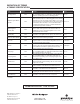
9 Reversed 120 VAC Line Polarity
or Bad Ground
- Verify the control and furnace is properly grounded.
- Check and reverse polarity (primary or secondary) if
incorrect.
10 Gas Flow with No Call for Heat
12 Ignitor Relay Failure Indicates the Ignitor relay contacts on the ignition
module are not functioning properly.
- Replace the ignition module.
Rapid Weak Flame Sensed Often caused by carbon deposits on the flame sensor,
a poorly grounded furnace or a mis-aligned flame
sense probe.
- Carbon deposits can be cleaned with emery cloth.
Check or improve furnace and module ground.
- Verify sensor is located in or very near flame as
specified by the appliance manufacturer.
- Refer to wiring diagram FS terminal and GND.
Blink
Continuous
Twinning error - Verify field installed wiring is connected correctly
- Verify both controls are model 50M56-801
Solid Internal Fault - Indicates a control fault that cannot be serviced
- Replace Control
1 Normal Heat Mode Operation No Fault
4 Y present with no G call No Fault
Solid Standby mode No Fault
Blink
continuous
Normal Fan Mode Operation (G) No Fault
1 Normal Operation with call for
cool (Y + G)
No Fault
2 sec ON
then OFF
Control Power ON Display
Indication
No Fault
off off off No Power - Verify Power to the control
- Replace control
Note: Continuous Blink flash code shall use 250ms ON time and 250ms OFF time for LED blink.
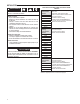
TROUBLESHOOTING