
Instructions / Assembly


7
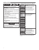
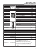
Term Location Definition Value
Y INPUT – low voltage thermostat Y terminal (or equivalent) 24 VAC
W INPUT – low voltage thermostat W terminal (or equivalent) 24 VAC
R OUTPUT – low voltage thermostat R terminal (or equivalent) 24 VAC
G
INPUT – 24 VAC low voltage thermostat G terminal
(or equivalent)
24 VAC
C COMMON – 24 VAC neutral side of compressor contactor coil N/A
HLO (Pin1)
OUTPUT – High limit
FS (Pin2) INPUT – Flame Sense
See
Electrical
Specs
TH (Pin 3) INPUT – Transformer (low voltage HIGH side) 24 VAC
PSO (Pin 4)
OUTPUT – Pressure Switch Output used to power external
normally open
24 VAC
RO (Pin 5) OUTPUT – Rollout switch OUTPUT 24 VAC
TR (Pin 6) INPUT – 24 VAC transformer (low voltage Neutral side) N/A
HLI (Pin 7) INPUT – High limit 24 VAC
GND (Pin 8) GND – MUST BE RELIABLY GROUNDED TO CHASSIS N/A
MV COM (Pin 9) COMMON – Gas Valve N/A
PSI (Pin 10) INPUT – Pressure Switch 24 VAC
ROI (Pin 11) INPUT – Roll out 24 VAC
MV (Pin 12) OUTPUT – Gas Valve 24 VAC
IND OUTPUT – Inducer 120 VAC
IGN OUTPUT – IGNITOR 120 VAC
IND-N COMMON – Inducer N/A
IGN-N COMMON – Ignitor N/A
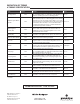
Fault Recall Button
Reference SYSTEM LOCKOUT & DIAGNOSTIC
FEATURES section
N/A
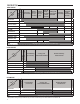
HEAT 1/4" spade terminal OUTPUT- circulator blower HEAT SPEED terminal 120 VAC
COOL 1/4" spade terminal OUTPUT-circulator blower COOL SPEED terminal 120 VAC
FAN 1/4" spade terminal OUTPUT-circulator blower FAN SPEED terminal 120 VAC
PARK (3 terminals) 1/4" spade terminal Unused circulator blower terminals N/A
LINE-H 1/4" spade terminal INPUT- Line Voltage 120 VAC
XFMR-H 1/4" spade terminal INPUT- transformer HOT side 24 VAC
EAC-H (optional) 1/4" spade terminal OUTPUT- Electronic Air Cleaner 120 VAC
HUM-H (optional) 1/4" spade terminal OUTPUT- Humidifier 120 VAC
24V HUM (optional) 1/4" spade terminal OUTPUT- Humidifier 24 VAC
NEUTRAL
(7 terminals)
1/4" spade terminal
Terminals for 120 Volt NEUTRAL for line, transformer,
circulator, electronic air cleaner and humidifier
N/A
Flame Sense (FS) 3/16" spade terminal INPUT-Remote Flame Sensor used on 81W03 and 74W03
See Electrical
Spec
Twinning (optional) 3/16" spade terminal
The “TWINNING” terminal shall be capable of providing
the control to be twinned with a same model control
produced by White-Rodgers. Connection of the
“TWINNING” terminals of each control together will allow
for simultaneous operation of two (2) furnaces or more and
forces the indoor blower motors of each furnace to operate
synchronously into a common ducting system. Enabling the
twinning function will require only field installed wiring with
no external kits or parts and no DIP switches will need to
be changed.
N/A
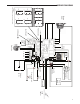
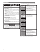
TH HLO
MV COM
FS
ROTR
GND
ROI
PSO
HLI
PSIMV
Terminal
block with
captive
screws
DEFINITION OF TERMS
& TIMING SPECIFICATION
IGN
IND
IND-N
IGN-N
FAULT RECALL