
Instructions / Assembly


CONTENTS
Preparations ...........................................
Thermostat Features ..............................
Removing Old Thermostat ......................
Mounting and Wiring ...............................
Set Heat Anticipator ................................
New Thermostat Operation .....................
Specifications .........................................
Troubleshooting ......................................
2
THERMOSTAT FEATURES
1
PREPARATIONS
Before removing wires from old thermostat’s switching subbase,
label each wire with the terminal designation it was removed
from. Some models also include an adaptor plate to cover
unpainted surfaces. Thermostat wires pass through the adaptor
plate center opening.
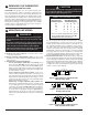
1. Remove Old Thermostat: A standard heat/cool thermostat
consists of three basic parts:
a. The cover, which may be either a snap-on or hinge type.
b. The base, which is removed by loosening all captive screws.
c. The switching subbase, which is removed by unscrewing the
mounting screws that hold it on the wall or adaptor plate.
Make a note here of the anticipator setting on
the old thermostat for future reference and use in step 5.
The heat anticipator pointer, if adjustable, will be set at one of a
series of numbers representing the current rating of the primary
control in your furnace. The number will be one of the following:
.2, .4, .8, etc. or 0.2, 0.4, 0.8, etc.
If no heat anticipator/indication is showing, do not be concerned;
move on to the next step.
PART NO. 37-7268A
1137
Failure to follow and read all instructions carefully before
installing or operating this control could cause personal
injury and/or property damage
Assemble tools required as shown below.
WIRE CUTTER/STRIPPER
SPIRIT LEVEL OR PLUMB BOB AND LINE OPTIONAL—
THERMOSTAT MUST BE LEVEL TO WORK PROPERLY
FLAT BLADE SCREWDRIVER
HAND OR POWER
DRILL WITH 3/16 INCH
DRILL BIT, IF NEEDED
To prevent electrical shock and/or equipment damage,
disconnect electrical power to the system at the main fuse
or circuit breaker until installation is complete.
CAUTION
!
1
2
3
4
5
6
7
8
Installation Instructions for
Model M100
SUBBASE
(MODEL 300
ONLY)
BASE
COVER
ANTICIPATOR
CAPTIVE SCREWS
MOUNTING SCREWS
Figure 1.
Adaptor Plate
(optional)
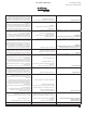
YOUR THERMOSTAT REPLACES
Description
Standard Heating & Cooling Systems- 4 or 5 wires Yes
Standard Heat Only System Yes
Millivolt Heat Only Systems- Floor or Wall Furnaces Yes
Standard Central Air Conditioning Yes
Gas or Oil Heat Yes
Electric Furnace Yes
Hydronic (Hot Water) Zone Heat - 2 Wires Yes
Hydronic (Hot Water) Zone Heat - 3 Wires No
Heat Pump (No Aux or Emergency Heat) No
Heat Pump (with Aux or Emergency Heat) No
Baseboard Electric Heating or Line Voltage (120 or 240 Volt) No
3
REMOVING OLD THERMOSTAT
www.white-rodgers.com