ELECTROLUX HOME PRODUCTS NORTH AMERICA SERVICE UPDATE MANUAL FOR 30” ELECTRIC FREESTANDING RANGES ! ATTENTION ! This service manual is intended for use by persons having electrical and mechanical training and a level of knowledge of these subjects generally considered acceptable in the appliance repair trade. Electrolux Home Products cannot be responsible, nor assume any liability, for injury or damage of any kind arising from the use of this manual.
Table of Contents SAFE SERVICING PRACTICES ............................... 3 SERVICE TIPS Develop Good Work Habits .................................. 4 Service Tools and Equipment ............................... 5 CHANGES AND FEATURES OVERVIEW ................ 5 ABBREVIATIONS AND TERMS ............................... 5 MODEL NUMBERING SYSTEM ............................... 6 SERIAL NUMBERING SYSTEM ............................... 6 RANGE TECHNICAL DATA..................................
SAFE SERVICING PRACTICES - ALL APPLIANCES To avoid personal injury and/or property damage, it is important that Safe Servicing Practices be observed. The following are some limited examples of safe practices: 1. DO NOT attempt a product repair if you have any doubts as to your ability to complete it in a safe and satisfactory manner. 2. Before servicing or moving an appliance: • Remove the power cord from the electrical outlet, trip the circuit breaker to the OFF position, or remove the fuse.
SERVICE TIPS - DEVELOP GOOD WORK HABITS Consistently following a standard procedure when servicing appliances will insure that you do not waste time searching for a complex solution to a simple problem. One of the most common mistakes made by service technicians is failing to verify the incoming power supply to the appliance. Many times electronic oven controls and other components are replaced unnecessarily because the incoming power supply was not verified.
SERVICE TOOLS AND EQUIPMENT In addition to standard hand tools such as wrenches, screwdrivers, pliers, etc; the following instruments are considered to be essential equipment for technicians servicing Electrolux cooking products. Proper testing and diagnostic procedures are not possible without these tools. • Volt/ohmmeter - Must be capable of voltage measurement from 0 to 500 volts AC and resistance measurements from 0 to 2 meg-ohms. This usually requires a meter that utilizes a 9 volt battery.
Model Numbering System for Free-Standing, Slide-in & Drop-in Ranges P L E F M* 3 9 9 D C A Brand Identifier PL = Professional GL = Gallery F = Frigidaire G = Gibson K = Kelvinator T = Tappan W = W/West M = Multiflex ECN Lot Identifier Required when ordering parts Color Code W = White (Zebra) S = White-on-White D = Almond (Zebra) T = Almond-on-Almond U = Bisque (Zebra) Q = Bisque-on-Bisque B = Black C = Stainless Steel /Black Range Fuel C = Combination (Electric/Gas) E = Electric (240/208v 60hz) F = Elect
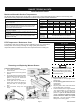
RANGE TECHNICAL DATA Quick Reference Sheet Maximum Allowable Surface Temperatures All gas and electric ranges must comply with U.L and A.N.S.I. surface temperature limits outlined in the following chart. Note that the testing temperature is different for electric ranges produced after 08/26/2003. SURFACE TEMPERATURE LIMITS MATERIAL TYPE / FINISH PAINTED 1. Product must be undamaged, correctly assembled and have the correct oven temperature. 2.
RANGE TECHNICAL DATA Electric Range Component Resistance Chart NOTE: Resistance measurments are approximate. Variations due to temperature changes and other factors are normal.
RANGE TECHNICAL DATA EOC Failure / Fault Codes On freestanding gas and electric ranges manufactured beginning with the serial number date code VF426 many of the EOC’s will have expanded three digit fault codes. These codes may also appear in new replacement EOC’s for ranges built prior to this date. Below is a list of possible fault codes that might appear in the EOC display window. The original two digit fault codes appear in the shaded boxes followed by the replacement three digit codes.
RANGE TECHNICAL DATA ESEC System Failure / Fault Codes Displayed Fault Code Description Suggested Corrective Action F5 A0 Bad EEPROM checksum. 1. Reset power supply to range. 2. Replace Power Board. F5 00 Communication break between EOC and UIB. 1. Reset power supply to range. 2. Test ESEC wiring harness. Replace if defective 3. Replace UIB 4. Replace EOC F5 01 Communication break between Power board & UIB 1. Reset power supply to range. 2. Test ESEC wiring harness. Replace if defective 3.
30” ELECTRIC ELECTRIC RANGE RANGE INSTALLATION INSTALLATION INSTRUCTIONS 30" INSTRUCTIONS (For 3 or 4 Wire, 60 Hz. Systems) INSTALLATION AND SERVICE MUST BE PERFORMED BY A QUALIFIED INSTALLER. IMPORTANT: SAVE FOR LOCAL ELECTRICAL INSPECTOR'S USE. READ AND SAVE THESE INSTRUCTIONS FOR FUTURE REFERENCE. Clearances and Dimensions 1. Provide adequate clearances between the range and adjacent combustible surfaces. 2. Location—Check location where the range will be installed.
30" ELECTRIC RANGE INSTALLATION INSTRUCTIONS (For 3 or 4 Wire, 60 Hz. Systems) BEFORE STARTING Tools You Will Need For leveling legs and Anti-Tip Bracket: to the wall, drill pilot hole at an approximate 20° downward angle (See Fig. 5). If bracket is to be mounted to masonry or ceramic floors, drill a 5/ 32" pilot hole 1-3/4" deep. The screws provided may be used in wood or concrete material. Use a 5/16" nut-driver or flat head screwdriver to secure the bracket in place (See Fig. 6). 1c.
30" ELECTRIC RANGE INSTALLATION INSTRUCTIONS (For 3 or 4 Wire, 60 Hz. Systems) See Range Connection Opening Size Chart (Figs. 9 & 10) for cord kit ampere rating information. Terminals on end of wires must be either closed loop or open-end spade lugs with upturned ends. 2b. MODELS REQUIRING POWER SUPPLY CORD KIT. RISK OF FIRE OR ELECTRICAL SHOCK MAY OCCUR IF AN INCORRECT SIZE RANGE CORD KIT IS USED, THE INSTALLATION INSTRUCTIONS ARE NOT FOLLOWED OR STRAIN RELIEF BRACKET IS DISCARDED.
30" ELECTRIC RANGE INSTALLATION INSTRUCTIONS (For 3 or 4 Wire, 60 Hz. Systems) 4B. POWER CORD CONNECTIONS (3-Wire Connection Instructions . For existing installations ONLY - Refer to Fig. 13). 1. Follow the manufacturer’s installation instructions supplied with the strain relief and install (Also see Figs. 9, 10 & 11). 2. Insert the end connectors for Line 1, Line 2 and Neutral and tighten securely to the terminal block (See Fig. 13).
SMOOTH GLASS COOKTOP SERVICING With the cooktop in the raised position the surface heating elements, warmer zone element and their wiring connections are accessible. The top can be held open by using a wood or plastic prop rod approximately 28 inches long. In the photos below a 1” diameter wooden dowel is used. Use caution not to damage the oven insulation blanket when placing the prop rod. The procedure for servicing the smooth glass cooktop and surface elements is the same as in previous models.
Removing and Replacing Surface Elements (continued) 5. Carefully pull the support channel away from the cooktop far enough to disengage the element mounting clips from the channel. Slide the element out from between the support channel and the cooktop. Reinstall or replace the element by reversing steps 1-5. Clip The element mounting clips must be removed from the original element and mounted to the replacement. The screw holes on the element body are numbered to identify the clip mounting locations.
Warmer Drawer Theory of Operation The circuit diagram below shows a typical wiring and control setup for a warmer drawer on an electric or gas range. The warmer drawer is designed to operate on 120 VAC. The L1 wire on the warmer drawer switch is connected to L1 in the power supply harness and the L2 wire on the switch is connected to the neutral circuit in the harness. When the switch is turned on the contacts L1-H1 close connecting the L1 circuit to one side of the warmer drawer element.
Servicing Warmer Drawer Components To service the warmer drawer body, drawer guides, or the element assembly first remove the warmer drawer by following the instructions on page 7 of this manual. Note that in order to release the latch on the right side of the drawer it is necessary to remove the latch lever shield by removing a ¼” hex head screw (see photo below). This screw and shield must be reinstalled when the drawer is replaced.
With the element and base pan assembly removed the element and thermostat are accessible for servicing. To dismount the element from the pan remove the screws and clips that secure it to the pan. Also remove the screw that secures the thermostat mounting bracket. Pull base pan forward to remove →→ When reinstalling the thermostat mounting bracket always insure that the element terminal shield is installed and properly positioned.
To Replace Oven Door: 1. Firmly grasp both sides of oven door along the door sides (Do not use the oven door handle). 2. Holding the oven door at the same angle as the removal position, seat the hook of the hinge arm over the roller pins located on each side of the oven door frame. 3. Fully open the oven door (horizontal with floor). 4. Push the door hinge locks up towards and into the oven frame on both left and right oven door hinges to the locked position. 5. Close the oven door.
Replacing Door Hinge Receptacle The door hinges engage steel pins in the hinge receptacles which are mounted on the back side of the front chassis. The following instructions will explain the steps necessary for the various styles of ranges that you may encounter. Begin by removing the oven door and warmer drawer or storage drawer as described in previous sections of this manual. WARNING Remove warmer drawer side shields. (Models With Warmer Drawer) Side Shield Screws 1.
Bodyside Mounting Changing the body side panel requires the removal of screws along the top and rear flanges and removing the two screws securing the front leg leveler to the chassis. When replacing the body side panels depending on the model there may be two hidden fasteners that must be addressed. The first is a screw on the inside flange of the body side just behind the face of the chassis as shown in the photo to the right.
Bake-N-Warm™ DOUBLE OVEN The Bake-N-Warm Double oven, or “Mini Oven” as it is commonly referred to, is located in the area normally used for the storage drawer. It can be used for baking or as a warmer drawer. See the photo at right. The Mini Oven is ideal for cooking foods such as pizza, casseroles, baked potatoes and frozen convenience foods. The mini oven temperature range is from 170º F to 450º F in bake mode, and from 150º F to 190º F in warmer drawer mode.
Diagnosing Mini Oven Failure If the mini oven fails to operate properly follow the same basic diagnostic steps that are used for any oven. Verify the power supply, check the wiring connections, test the heating element and temperature sensor probe. Use extreme care when testing circuits with live voltage present. If the mini oven control fails to send voltage to the element perform the following tests to determine the cause of failure. 1.
Mini Oven Component Service Replacing Mini Oven Element Fig. 1 Remove Drawer 1. Before drawer removal, be sure to turn OFF the Bake-n-Warm™ Double Oven and let the drawer area cool completely. 2. Open the drawer to the fully open position. Using a phillips-head screwdriver remove the two drawer screws from the insides of the front oven drawer compartment (See Fig. 1). 3. With one hand hold the drawer front in place. Use your other hand to pull the glide away from the oven (See Fig.
Replacing Drawer Glide Rails The mini oven drawer glide rails (Fig. 8) clip into the side wall of the mini oven cavity and are secured by one screw in each rail. Fig. 8 The mounting screw is accessed through a hole in the glide rail outer track. (Fig. 9) . Fig. 9 Remove Screw Once the mounting screw is removed extend the outer track of the glide rail until it stops. Pull forward firmly until the hooks on the back of the rail disengage from the slots in the oven cavity side wall. ( Fig. 11 & 12 ) Fig.
Mini Oven Chassis The mini oven chassis can be removed as an entire assembly. Begin by disconnecting the wire harness connections to the element and cavity light. Remove the drawer per instructions on page 26. Screw Access Using a ¼” nut driver with magnetic screw holder remove the two screws securing the mini oven chassis to the range chassis. These screws are accessed through the holes in the mini oven cavity liner just below the drawer glide rail. (Photo A).
Electric Range Component Resistance Chart NOTE: Resistance measurments are approximate. Variations due to temperature changes and other factors are normal.
Electronic Oven Controls The newest generation of Electronic Oven Controls have significant improvements to make them easier for the consumer to operate and provide enhanced diagnostic tools for the service technician. Below are examples of the current control configurations that can be found on freestanding electric self cleaning ranges. The controls for non self clean ranges have not changed.
ES 340 Control Features: ES 340 CONTROL • Automatic oven (Delay, Cook, and Off) • Full slew up / down control • Digital Time and Temperature Display • Electronic Clock and Countdown Timer (12 Hour) • Dual Radiant™ Baking (electric models) • Variable broil (2 positions) • 2 Pre - programmed clean cycles (2 hour Speed clean - 3 hour Clean ) • 12 hour energy saving shut-off with override for continuous operation • Selectable Fº or Cº temperature readout • Control Lockout (disables oven and locks door) • Oven
Troubleshooting Electronic Oven Controls When an oven with an electronic control detects a failure condition, it usually signals the failure with an “F” code. These “F” codes are considered by many people to be an indicator as to positively which part in the circuit has failed (“F1” a defective control, “F3” a defective oven probe, and so on). To the embarrassment of many servicemen who have believed this, they have installed the indicated part only to find it did not correct the problem.
EOC FAILURE / FAULT CODES On freestanding gas and electric ranges manufactured beginning with the serial number date code VF426 many of the EOC’s will have expanded three digit fault codes. These codes may also appear in new replacement EOC’s for ranges built prior to this date. Below is a list of possible fault codes that might appear in the EOC display window. The original two digit fault codes appear in the shaded boxes followed by the replacement three digit codes.
ES 510 ELECTRONIC OVEN CONTROL The ES510 control is found on electric ranges with the ESEC 10R system. It has some unique features and functions not found on other EOC’s. This section of the manual provides specific service information for the ES 510 Electronic Oven Control. The ES510 controls the bake element, broil element, oven light, latch lock motor, convection fan motor and convection element.
F11 ERR - Shorted control keypad. Disconnect power, wait 30 seconds and reapply power. If fault returns upon power-up, replace EOC. NOTE: This failure code can be induced by holding down on a keypad for more than 20 seconds. F20 ERR - Communication failure between EOC and ESEC system. Test harness/connections P4 on EOC & P11 on Surface element control board. If harness checks O.K. failure can be caused by faulty UIB, surface element control board, or EOC.
ES510 EOC RELAYS - CIRCUIT TEST MATRIX The EOC relay circuits can be tested by following the circuit test matrix at right. Always verify the incoming power supply when performing diagnosis.
ELECTRONIC SURFACE ELEMENT CONTROL (ESEC) SYSTEM VERSION 10R The Electronic Surface Element Control System ,(ESEC), precisely controls the smoothtop cooking elements at multiple settings. (The Warming Zone element is not controlled by the ESEC). For the user, the elements are operated in the same way as with conventional controls, by pushing in and turning the knob to the desired setting. The setting is shown in the digital display above the knob, instead of using graphics on the control panel.
How The ESEC System Operates When the user rotates the surface element control knob to the desired setting the User Interface Board (UIB) responds by displaying the selection on the ESEC display board and communicating the selection information to the power board. The power board then cycles the surface element on at the appropriate percentage to the power level selected.
ESEC Failure / Fault Codes Displayed Fault Code Description Suggested Corrective Action F5 A0 Bad EEPROM checksum. 1. Reset power supply to range. 2. Replace Power Board. F5 00 Communication break between EOC and UIB. 1. Reset power supply to range. 2. Test ESEC wiring harness. Replace if defective 3. Replace UIB 4. Replace EOC F5 01 Communication break between Power board & UIB 1. Reset power supply to range. 2. Test ESEC wiring harness. Replace if defective 3. Replace UIB. 4.
The photos below show the potentiometers and the display boards mounted to the range backguard panel. The potentiometers are held in place by a hex nut and lock washer. When replacing a potentiometer, do not over-tighten the hex nut. A torque of only 5 in.-lbs. is required to properly mount the potentiometer. Over-tightening the hex nut will negatively affect the smooth feel of the knob turn and can damage the potentiometer.
Display Boards The display boards are secured to the control panel by the display lenses. The lens is inserted into the panel from the front and the display board locks onto the lens from behind. The following instructions explain how to separate the board from the lens and remove the lens from the control panel without damage. The board is secured to the lens by two locking tabs (Photo 1) .
User Interface Board The UIB is mounted to the rear chassis of the range just below the control panel backguard. Prior to removing the UIB unplug the wire harness connectors to the display boards and power board. DO NOT ATTEMPT TO UNPLUG THE HARNESS CONNECTORS TO THE POTENTIOMETERS. These connectors and harness wires are part of the UIB. Unplug the harness connectors at the potentiometers to replace the UIB. The UIB is secured to the range with one mounting screw and two snap-lock spacers.
The photo below shows an ESEC Power Board and Remote Relay Board as they appear when installed on a range. When replacing the Power Board or Remote Relay Board do not over-tighten the screws. A torque of only 10 in.-lbs. is required to tighten the screws. Over-tightening the screws can damage the plastic standoffs and possibly the board itself.
DIAGRAM A DIAGRAM B Page 43 P/N 316439220