
Specifications


FTB 312-4 Revision 4 – 1-8-2008 33
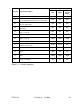
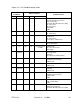
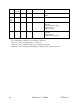
Figure 3-2 – Unit Troubleshooting Guide
Flash
Conditions
Other Conditions
Probable Causes
Day
Night
HV
1
LV
2
No No OK OK FT101 Flashtube
Flashhead Cable Connections
T101 Transformer
Flashtube Mounting Plate Assembly
4
T1 Transformer
T3 Transformer
BR1 Bridge
PCB1
No No No No Blows Fuse F1 Varistor MOV
T1 Transformer
No No No No F1 Fuse
S1 Interlock
T1 Transformer
Connections – Main Power
No No No OK C2A-D or C3 Shorted
Shorted FH Cable
No No OK No No indicators lit
on PCB1
PCB1 Board
T1 Power Transformer
BR1 Bridge
OK High
Intensity
OK OK Red Alarm PCB1 Board
Photocell Circuit
K2 Relay
Intensity Select Switch Setting
OK OK OK OK Markers Out F4 Fuse
K5 Marker Control Relay
3
PCB1 Board
OK OK OK OK Markers Stay On K5 Marker Control Relay
3
PCB1 Board
OK Backup
Intensity
OK OK Flashtube Mounting Plate Assembly
4
K2 Relay
PCB1 Board
OK OK OK OK Marker Alarm One or More Marker Lamps Out
K5 Marker Control Relay
3
PCB1 Board
PCB3
- - OK OK Incorrect Mode S2 Intensity Select Switch Not in AUTO
PEC or PEC Wiring
PCB1
OK No OK OK Red Alarm C3 Capacitor
Trigger Steering Relay
Flashtube Mounting Plate Assembly
4