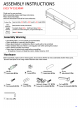
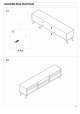
ASSEMBLY INSTRUCTIONS LVI TV 15130WI Thank you for you purchase. Before assembly, please read these instructions. Please read all warnings. Store this instruction manual for future reference. Product Size Approximately 350 Width x 1800 Length x 469 Height (MM) Main y a Materials MOF {Medium Density Fiberboard)} Weight Top insert: About 40KG, Shelf insert: About 10KG, Capacity X These are measured figures, not guaranteed figures, Time To Miserably.
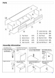
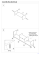
Parts 5 Cater Panel Center Panel (R} 1Pc¢ Shelf Panel 1Pc Big Door Panel 2 Pes “1° Top Panel 1 Pc {2} Bottom Panel 1Pc 3 Side Panel {L} 1Pc 9 "Small Door Panel 1 Pc 4) Sideline) 1Pe (10 Back Moldboard 1Pe Assembly Information = Assemble screws = Assemble Wood Dowels = Assemble Mini fix 1. Screw up to half pain to make sure all spots are lined up ~ 1. Insert dowels into holes 1. Screw Up Mini fix M5X24MM tightly . Insert Mini fix Casing into into holes. Tighten all Mini fix. holes.
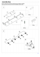
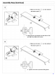
Assembly Step Failure to follow these directions could cause poor strength or stability, Insert screws loose to line up with slots then tighten up each screw.
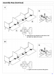
Assembly Step (Continue) 5 # Make sure the door. 2 }.is in the middle of the bottom panel { 9 [74 Adjust the door by moving it up and down of left and right then tighten the screws. # Make sure the door 2 is in the middle of the bottom panel ) ~ Tighten the screws to prevent sliding doors.
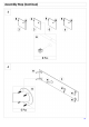
Assembly Step (Continue) Make sure the door in the correct position # Adjust.
Assembly Step (Continue) 9 [og Adjust the door by moving it up and down or left and right then tighten the screws. Tighten the screws to prevent sliding doors.
Safety Please read the below warnings before use. Failure to follow these warnings could result in serious injury. CAUTION HH Purpose = Do not ise this unit except for original application = This unit is for household use. Do not use it for wholesale. = This unit is for indoor use. Do not use it outside.
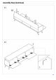
HOW TO ADJUST GLASS/DOORS @® There is a gap between the door and the shelf with doors closed Loosen the back adjustable screw which is ane of the two screws looking from the front whi supporting the doors, adjust the door by moving it back and forth, then tighten the back screw. N Loosen this screw, adjust by moving back and forth -if there is a gap between the doors on 5 the top.
-~Part include CANTETIP™ 4 WITH ANTE TIP Installation Instruction : A tip restraint must be attached to a wall stud using the 27 screw sh closed. Attach a strap to the back top ral or back top edge of the furniture using the 5/8" screw provided. Locate the strap on the wall over a wall stud. and 2 inches. below. the mounting strap secured to the back of your uni. Attach to the wall stud using the 2" screw provided, through the smaller-hole.