
Installation Guide
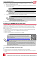

3.
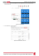
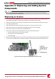
PullouttheRS485terminalblockconnector,asshownbelow:
Figure 29: The RS485 terminal block
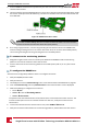
4.
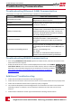
LoosenthescrewsofpinsA(+),B(-),andGontheleftoftheRS485terminalblock(RS485-1).
Figure 30: RS485 terminal block
5.
InsertthewireendsintotheG, AandBpinsshownabove.UseFour-orsix-wiretwistedpaircablefor
thisconnection.
YoucanuseanycolorwireforeachoftheA,BandGconnections,aslongas:
l ThesamecolorwireisusedforallApinsthesamecolorforallBpinsandthesamecolorforallG
pins
l ThewireforGisnotfromthesametwistedpairasAorB.
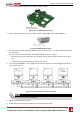
6.
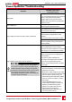
ForcreatinganRS485bus-connectallB,AandGpinsinallinverters.Thefollowingfigureshowsthis
connectionschema:
Figure 31: Connecting the inverters in a chain
NOTE
Do not cross-connect B, A and G wires.
7. Tightentheterminalblockscrews.
8. Checkthatthewiresarefullyinsertedandcannotbepulledouteasily.
Chapter 6: Setting Up Communication
-Single Phase Inverter with HD-Wave Technology Installation MAN-01-00541-1.0
51