
Installation Manual


7
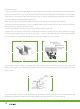
(d)
(f)
(e)
(g)
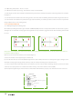
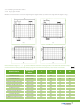
3.2.2 Clamping on the frame surface
3.2.2.1 Single glass module
Modules can be laid either across the supporting bars (Figure d & f) or parallel to the edge of frame (Figure e & g ) .
Remark: Illustrations ( gure d
、
e
、
f
、
g) of the four di erent methods for clamping modules on the frame with aluminum clamps. “
”
means the aluminum clamp’s permissible clamping range.The recommended installation position shows as below table:
Module Series
Dimension
A*B*C
J K L M
CHSM6610P/(FR) 1648*990*35 198 408 --- ---
CHSM6608M/(/HV) 1332*990*40 198 328 50 200
CHSM6610M/(BL)/(FR)/(/HV) 1648*990*40 198 408 50 200
CHSM6610P/(BL)/(BF)/(/HV) 1648*990*40 198 408 50 200
CHSM6612P/(/HV) 1954*990*45 479 499 --- ---
CHSM6612P/(FR)/M/(/HV) 1954*990*40 299 489 50 200
CHSM6612M/(/HV) 1954*990*40 299 489 50 200
DIAMOND CHSM6612P/(/HV) 1954*990*40 299 489 50 200