
Installation Guide


FLUSH MOUNT INSTALLATION MANUAL - 5©
2016 IRONRIDGE, INC. VERSION 1.10
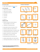
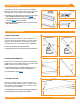
3. SECURE LUGS
Insert T-bolt in top rail slot and torque hex nut to 80 in-
lbs. Install a minimum 10 AWG solid copper or stranded
grounding wire. Torque terminal screw to 20 in-lbs.
í Grounding Lugs are only needed on one rail per row of modules
(unless frameless modules are being used, see Page 8).
í If using Enphase microinverters, Grounding Lugs may not be
needed. See Page 8 for more information.
í Grounding Lugs can be installed anywhere along the rail and in
either orientation shown.
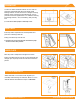
4. SECURE MODULES
A. SECURE FIRST END
Place rst module in position on rails, a minimum of 1”
from rail ends. Snap Stopper Sleeves onto UFO. Fasten
module to rail using the UFO, ensuring that the UFO is
hooked over the top of the module. Torque to 80 in-lbs.
í Ensure rails are square before placing modules.
í Hold Stopper Sleeves on end while torquing to prevent rotation.
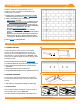
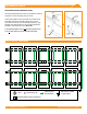
B. SECURE NEXT MODULES
Place UFO into each rail, placing them ush against rst
module. Slide second module against UFO. Torque to 80
in-lbs. Repeat for each following module.
í When reinstalling UFO, move modules a minimum of 1/16" so
UFOs are in contact with a new section of module frame.
í If using Wire Clips, refer to Page 7.
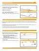
C. SECURE LAST END
Place last module in position on rails, a minimum of 1”
from rail ends. Snap Stopper Sleeves onto UFO. Secure
UFO Clamps on rails, ensuring they are hooked over top
of module. Torque to 80 in-lbs.
í Hold Stopper Sleeves on end while torquing to prevent rotation.
í Repeat all steps for each following row of modules.
A
B
Hex Nut
(84 in-lbs)
Terminal Screw
(20 in-lbs)
C
Hex Nut
(80 in-lbs)
1" From
Rail End
UFO
(80 in-lbs)
Stopper
Sleeve
UFO
(80 in-lbs)
UFO
(80 in-lbs)