
Installation Guide


FLUSH MOUNT INSTALLATION MANUAL - 6©
2016 IRONRIDGE, INC. VERSION 1.10
EXPANSION JOINTS
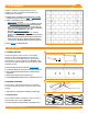
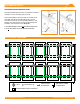
ELECTRICAL DIAGRAM
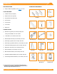
GROUNDING STRAP EXPANSION JOINT
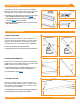
Grounding Strap Expansion Joints are required for thermal
expansion of rows exceeding 100 feet of rail.
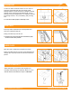
Insert Internal Splice into rst rail and secure with screw.
Assemble and secure Grounding Strap 3/8" from rail
end. Slide second rail over Internal Splice leaving 1" gap
between rails. Attach other end of Grounding Strap with
hardware, and torque hex nuts to 80 in-lbs.
í Second Bonded Splice screw is not used with Expansion Joints.
í Do not install module over top of expansion joint location.
Fully Seat
Screw 1" Gap6" Inside Rail
3/8" From End
Torque to
80 in-lbs
UFO
Grounding Lug
Minimum 10 AWG
Copper Wire
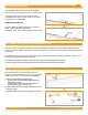
Fault Current
Ground Path
Bonded Splice (Rail Connection)
*Grounding Lugs and Wire are not required in systems using Enphase microinverters.
*
*