FLUSH MOUNT INSTALLATION MANUAL
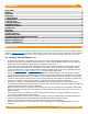
CONTeNTS DISCLAIMeR RATINGS MARKINGS CHeCKLIST 1. ATTACH BASeS 2. PLACe RAILS 3. SeCURe LUGS 4. SeCURe MODULeS eXPANSION JOINTS eLeCTRICAL DIAGRAM FLASHFOOT2 eND CAPS WIRe CLIPS FLUSH STANDOFFS MICROINVeRTeR KITS SYSTeMS USING eNPHASe MICROINVeRTeRS FRAMeLeSS MODULe KITS MODULe COMPATIBILITY MODULe COMPATIBILITY 1 2 2 3 4 4 5 5 6 6 7 7 7 7 8 8 8 9 10 DISCLAIMeR This manual describes proper installation procedures and provides necessary standards required for product reliability.
RATINGS UL 2703 LISTeD #5003320 #5003807 • Conforms to STD UL 2703 (2015) Standard for Safety First Edition: Mounting Systems, Mounting Devices, Clamping/ Retention Devices, and Ground Lugs for Use with Flat-Plate Photovoltaic Modules and Panels. • Max Overcurrent Protective Device (OCPD) Rating: 25A • Max Module Size: 24ft² • Module Orientation: Portrait or Landscape • Allowable Design Load Rating: meets minimum requirements of the standard (10 PSF downward, 5 PSF upward, 5 PSF lateral).
CHeCKLIST PRe-INSTALLATION IRONRIDGe COMPONeNTS ☐ Verify module compatibility. See Page 9 for info.
1. ATTACH BASeS Install roof attachments. Mount Slotted L-Feet, FlashFoot2, or other compatible roof attachment per manufacturer's instructions. í IronRidge's all-in-one FlashFoot2 roof attachment is for pitched, composition shingle roofs. Refer to Page 7 or provided manual. í Tested or evaluated third-party roof attachments: • Anchor Products - U-Anchor • S-5! Standing Seam Metal Roof Clamps - Certification of metal roof clamps includes bonding to both painted and galvalume metal roofs.
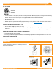
3. SeCURe LUGS Insert T-bolt in top rail slot and torque hex nut to 80 inlbs. Install a minimum 10 AWG solid copper or stranded grounding wire. Torque terminal screw to 20 in-lbs. Terminal Screw (20 in-lbs) í Ground Lugs are only needed on one rail per continuous row of modules, regardless of row length (unless frameless modules are being used, see Page 8). í If using enphase microinverters, Grounding Lugs may not be needed. See Page 8 for more information.
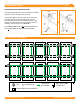
eXPANSION JOINTS GROUNDING STRAP eXPANSION JOINT Grounding Strap Expansion Joints are required for thermal expansion of rows exceeding 100 feet of rail. 3/8" From End Torque to 80 in-lbs Insert Internal Splice into first rail and secure with screw. Assemble and secure Grounding Strap 3/8" from rail end. Slide second rail over Internal Splice leaving 1" gap between rails. Attach other end of Grounding Strap with hardware, and torque hex nuts to 80 in-lbs.
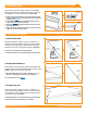
FLASHFOOT2 Locate roof rafters and mark locations on roof. Drill 1/4” pilot holes and backfill with approved sealant. Slide flashing between 1st and 2nd course of shingles, ensuring flashing doesn't overhang the downhill shingle. Line up with pilot hole and insert supplied lag bolt with washer through flashing. Fully seat lag bolt. Place Cap onto flashing in desired orientation for E/W or N/S rails and rotate 180 degrees until it locks into place. í Rail can be installed on either side of FlashFoot2 Cap.
MICROINVeRTeR KITS Use IronRidge's Microinverter Kit to bond compatible microinverters and power optimizers to the racking system. Insert Microinverter Kit T-bolt into top rail slot. Place compatible microinverter or power optimizer into position and tighten hex nut to 80 in-lbs.
MODULe COMPATIBILITY The Flush Mount System may be used to ground and/or mount a PV module complying with UL 1703 only when the specific module has been evaluated for grounding and/or mounting in compliance with the included instructions. Unless otherwise noted, “xxx” refers to the module power rating and both black and silver frames are included in the certification.
MODULe COMPATIBILITY MAKe MODeLS Mitsubishi Modules with 46mm frames and model identifier PV-MYYxxxZZ; where "YY" is LE or JE; and "ZZ" is either HD, HD2, or FB. Motech IM and XS series modules with 40, 45, or 50mm frames. Neo Solar Power Modules with 35mm frames and model identifier D6YxxxZZaa; where "Y" can be M or P; "ZZ" can be B3A, B4A, E3A, E4A, H3A, H4A; and "aa" can be blank, (TF), ME or ME (TF).