Development Kit User Guide – Rev11.0 9706 4th Ave NE- Suite 208 Seattle, WA 98115 206-580-09007 http://www.wibotic.com info@wibotic.com Prepared by: WiBotic Inc Date Updated: Revision 11.0 – July 14, 2020 Notice: This document is provided for informational purposes only. It represents WiBotic’s current product offerings and practices as of the date of issue of this document, which are subject to change without notice.
Development Kit User Guide – Rev11.
Development Kit User Guide – Rev11.0 Contents Description ..................................................................................................................... 6 Key Features ................................................................................................................. 6 Development Kit Configuration ...................................................................................... 7 Inside the Box ......................................................................
Development Kit User Guide – Rev11.0 Update Button ....................................................................................................... 35 “Data Plots” Menu .................................................................................................... 38 “About” Menu ........................................................................................................... 38 Wireless Power Transmission ................................................................................
Development Kit User Guide – Rev11.0 CAN API ................................................................................................................... 58 Basic Setup .......................................................................................................... 59 Talking over CAN .................................................................................................. 60 Provided Code .............................................................................................
Development Kit User Guide – Rev11.0 Description WiBotic wireless power solutions enable autonomous wireless charging of mobile robots, aerial drones, unmanned aquatic vehicles, and other industrial automation devices across a wide range of applications. For simplicity and consistency, we refer to all of these vehicles, drones, and devices as “robots” for the remainder of this User Guide. The WiBotic Development Kit is the first step in automating power delivery to robots or entire robot fleets.
Development Kit User Guide – Rev11.0 Development Kit Configuration The following diagram shows the operational configuration of the system as well as the individual components supplied with every WiBotic Development Kit: Inside the Box 1. 2. 3. 4. 5. Ethernet Cable USB to Ethernet Adapter Power Cable Power Transmitter (TR) Onboard Charger (OC) 6. 7. 8. 9.
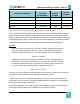
Development Kit User Guide – Rev11.0 Specifications All WiBotic Wireless Power systems share the following standard specifications: PARAMETER RANGE Wireless Power Operating Frequency 6.78 ± 0.015 MHz Communication Link Frequency 2.433 - 2.
Development Kit User Guide – Rev11.0 OUTPUT VOLTAGE (TO BATTERY)* MAX OUTPUT POWER OUTPUT CURRENT OC-110 7.92 - 30.1 VDC 90W 0.5 - 5A OC-210 12.03 – 36.0 VDC 125W 0.5 - 10A OC-250** 12.03 – 36.0 VDC 250W 0.5 - 10A 0 - 58.4 VDC 300W 0.5 - 30A ONBOARD CHARGERS OC-300 *DC Output voltage and current is configurable within the specified range via WiBotic software or API. **The OC-250 can be configured for higher output voltage up to 58.4V if required.
Development Kit User Guide – Rev11.0 Initial Hardware Setup For initial system familiarization, WiBotic highly recommends bench-top testing. This allows the system to be operated in open air and at various power levels and antenna positions – demonstrating the unique flexibility of WiBotic’s technology. Note: WiBotic does not recommend immediate installation of the wireless power system on robots for testing purposes.
Development Kit User Guide – Rev11.0 Repeat the process for the receiver antenna – again using longer M3 screws to more securely affix the antenna to the bracket. Note that the receiver antenna enclosure does not have a vented back side. When mounting this antenna, be sure that the side of the enclosure with the embossed WiBotic logo is facing the transmitter antenna. To move the antennas relative to one another, simply loosen the thumb screws and slide both antennas within the T-Base channels.
Development Kit User Guide – Rev11.0 TRANSMITTER ONBOARD CHARGER/RECEIVER 4. With the antenna coils mounted on the coil stands, loosen the thumb screws and adjust the coil enclosures so they are concentric and approximately 20mm apart. This will be the starting position for testing, but you may then move the coils in and out and side to side during testing. You may also twist one or both coils to experience power transfer when the coils are not parallel.
Development Kit User Guide – Rev11.0 CAUTION: Do not place the Transmit Coil on a metallic surface, and make sure that all metal objects are at least 30cm away from the Transmit and Receive Coils during testing. CAUTION: Removing the antenna coils from their enclosures is not recommended without guidance from WiBotic. High voltage exists on antenna coil components during charging. DO NOT touch any portion of a bare antenna coil during charging. 5.
Development Kit User Guide – Rev11.0 The following diagrams show the various connectors on each OC and the pin-out of each male battery output connector. Use these diagrams to properly wire the corresponding female connectors.
Development Kit User Guide – Rev11.0 from the transmitter it may be easier to charge robot in place rather than manually pushing it back to the transmitter station. Also, for some customers the WiBotic OC may be used as a programmable plug-in charger at first and then upgraded to wireless charging in the future by adding a receiver antenna and transmitter station. For these reasons, the OC-210, OC-250 and OC-300 all have a six-pin Molex MiniFit Jr. auxiliary DC power input port.
Development Kit User Guide – Rev11.0 Configuring Ethernet Connectivity The WiBotic Web GUI allows users to control the WiBotic system, view its status, and make changes to settings without having to install separate software. The interface is accessible via modern versions of Firefox, Chrome, Edge, and Safari. A direct point-topoint Ethernet connection is recommended for initial setup although networking is possible through the Network Setting menu.
Development Kit User Guide – Rev11.0 4. Select Internet Protocol Version 4 (TCP/IPv4) and click the Properties button below it: 5. Click the Use the following IP address button and specify the following settings. The DNS section may be left blank. Click OK: IP address: Subnet mask: Default gateway: 192.168.2.10 255.255.255.
Development Kit User Guide – Rev11.0 6. After the network settings have been configured, open a Web Browser (Firefox, Chrome, or Edge) and go to the following URL: http://192.168.2.20 7. Verify that the web application loaded and that the Transmitter status at the top of the screen shows “Idle”. Linux (Temporary Connection) 1. Open a terminal window (many desktop environments have a keyboard shortcut CTRL+ALT+T to do this). 2.
Development Kit User Guide – Rev11.0 Linux (Permanent Connection) or Another OS Please refer to the network setup guide for your operating system. You will need the following information: Static IP (for the computer you are setting up): Static IP (for the WiBotic transmitter): Subnet Mask: 192.168.2.10 192.168.2.20 255.255.255.
Development Kit User Guide – Rev11.0 4. Open a browser (Chrome) and navigate to http://192.168.2.20 to access the WiBotic GUI. Ethernet Configuration Reset If the WiBotic system does not seem to be responding on the default IP address, you can attempt to reset the Ethernet configuration to the default factory settings. 1. Locate a thin rigid object such as a small hex key or an unfolded paperclip. 2. Gently insert the object into the hole located on the Transmitter just below the Ethernet jack.
Development Kit User Guide – Rev11.0 3. Upon inserting the thin rigid object, you should feel a button that depresses about 1mm. Hold the object on that button for more than 5 seconds. 4. Upon releasing the button, the LCD screen (if equipped) on the front of the transmitter will turn magenta and display “Ethernet Config Reset”.
Development Kit User Guide – Rev11.0 Web GUI Functions Once the network connection has been established, all system cables have been connected, and the antenna coils are within the ideal operating range, you’re ready to open the Web GUI to begin experiencing WiBotic wireless power! Important Note: Once again, testing the system on a benchtop is highly recommended as a first step. This will ensure the system is operating correctly at the full range and power level it can provide.
Development Kit User Guide – Rev11.0 of the Transmitter (about 30ft). While wireless power obviously cannot be sent to a Charger in this state, the Transmitter is able to see the status of the Charger and connected battery, change settings, and perform firmware updates. This is called “Distance Connect Mode” (see section later in document).
Development Kit User Guide – Rev11.0 Live data related to each component is displayed on the Control Panel, and battery settings are shown just to the right of the battery image. A more detailed view of all parameters is accessible via the “Switch to Data View” button in the upper right corner of the main display. “Settings” Menu The Settings menu provides four sub-menus that allow for customized system operation: 1.
Development Kit User Guide – Rev11.0 Charging stops when the float voltage for the pack is reached and the current being delivered to the battery drops to 1/10th of the maximum current setting. It is normal for battery voltage to sag immediately after charging stops, and it would be impractical for the system to immediately resume charging to again reach the float voltage. Therefore, a default “Restart Threshold” is built into the system based upon known characteristics for various battery chemistries.
Development Kit User Guide – Rev11.0 these adjustments based upon the robot’s duty schedule lets users truly maximize the lifespan of entire fleets of batteries. WiBotic charging systems can be used with a wide range of battery types – including a range of both protected and unprotected Lithium chemistries. The “Enable Recovery Charge” mode is particularly useful when Protected batteries are used.
Development Kit User Guide – Rev11.0 are met. This protects the battery cells, avoiding potentially dangerous failures and extending overall battery life. In these cases, since permanent damage to the cells has been prevented, it is acceptable to “wake up” the battery so charging can resume. This mode of operation can is allowed by activating the Enable Recovery Charge (ERC) toggle switch on the Battery Settings page.
Development Kit User Guide – Rev11.0 WARNING: Please confirm the battery requirements to ensure the charge current and voltage are within permissible limits for your battery. Damage to the battery, charger or connected equipment may occur if incorrectly configured. A damaged battery could cause fire or personal injury. Charge Settings The Charge Settings sub-menu allows users to configure the system for autonomous operation. It also provides for “Charge Cycle” and “Top-off Period” time limits.
Development Kit User Guide – Rev11.0 In the above image, the transmitter is disabled/off so users will need to manually flip the toggle switch in the upper right corner of the Web GUI any time the system is repowered and they would like a robot to start charging. However, if fully automatic operation is desired, simply click on both the transmitter and charger toggle switches and then click the black “Save default state as…” button immediately below.
Development Kit User Guide – Rev11.0 Finally, the “Maximum Top Off Charge Time” is also a user-adjustable variable. This setting determines how long the charger will remain in “Constant Voltage” mode at the end of a charge cycle. Normally, current slowly drops during CV mode until it reaches 1/10th (C/10) of the Maximum Charge Current value. The charger then turns off and waits for battery voltage to drop to the “Restart Threshold” before starting to charge again.
Development Kit User Guide – Rev11.0 CAN Settings The CAN Settings sub-menu provides configuration parameters for CAN-bus communications between the Onboard Charger and the robot/drone controller. See Appendix C for a complete discussion of WiBotic’s Onboard API and related CAN-bus setup and functionality. “Diagnostics” Menu The WiBotic Development Kit is intentionally configured for in-air operation using the supplied antenna coil mounting brackets.
Development Kit User Guide – Rev11.0 Onboard Charger closer to each other. The system will shut down and enter heartbeat mode. TX Alarm: Power transfer too low This usually occurs when the coils are positioned too far apart or in a nonoptimal orientation. Transmitter will immediately shut down. Try repositioning the coils if this alert persists. TX Info: Internal communication error An internal error might occur that will cause the system to restart. The system will restart and enter heartbeat mode.
Development Kit User Guide – Rev11.0 Log Messages The Log Messages section allows users to view and download separate log files for the Transmitter and Onboard Charger – typically for troubleshooting with assistance from WiBotic. The “System Log” file contains a chronological record of all system events since the Transmitter was last powered on. It is similar to the Live Log above, but the System Log file is not date/time stamped and is not affected by closing the browser.
Development Kit User Guide – Rev11.0 version, you are encouraged to install it directly. If you must step through the installation of more than one version, notes will be available advising you of the proper sequence. Under the heading for each firmware version will be a series of files for download. A new version of the Web GUI interface may be made available with enhanced features as well as new .bin files for the transmitter and receiver.
Development Kit User Guide – Rev11.0 The recommended order of upload from your computer to the transmitter is 1) WEB.RFS, 2) Transmitter Firmware, and 3) Onboard Charger Firmware. You will notice a slight flash and reload of the Web GUI when the WEB.RFS file is uploaded. Update Button After completing the above steps, you will use the lower portion of the Update page to actually install the new firmware onto the Transmitter and Onboard Charger circuits.
Development Kit User Guide – Rev11.0 After the update is complete, the Current Firmware Version shown in the page under the Transmitter section should match the firmware version under Uploaded Firmware Version as shown in the red and green boxes above. If the system takes more than 5 minutes to update, first try refreshing the web page to see if the firmware may have updated, but just not refreshed the page.
Development Kit User Guide – Rev11.0 After the update is complete, the “Current Firmware Version” and “Uploaded Firmware Version” for the Onboard Charger should match. Note that it may take several seconds for the web page to update after the status bar indicates “Update Complete”. During this time, the Current Firmware Version may be shown as “Unavailable”. If the system takes more than 5 minutes to update, restart both the Onboard Charger and the Transmitter and try again.
Development Kit User Guide – Rev11.0 At this point your system’s firmware has been updated and you can begin to enjoy the new features and performance. “Data Plots” Menu The Data Plots menu provides a graphical representation of various system parameters over time. To choose the displayed parameters, click on the Parameter pull down menu on the right side of the screen. You may also reset the default scale for that parameter by typing a new value in the Scaling Factor box immediately below.
Development Kit User Guide – Rev11.0 Wireless Power Transmission To begin testing wireless power, first confirm that the System Status “Charger” toggle switch in the upper right corner is in the default “On” position and the “Transmitter” toggle switch is in the default “Off” position. Next, turn the Transmitter on by clicking the Transmitter toggle switch. If there is an Onboard Charger ready to accept power, and it is within range of the transmit coil, the system will now enter its charging sequence.
Development Kit User Guide – Rev11.0 About the Battery Charging Process WiBotic Onboard Chargers are configured by default to act as Constant Current/ Constant Voltage (CC/CV) battery chargers. If the Transmitter is physically powered, the Transmitter toggle switch is turned on, and an Onboard Charger is in range, the system will begin charging if the battery is not already considered fully charged.
Development Kit User Guide – Rev11.0 The GUI will indicate that the battery is fully charged by displaying “Battery Full” as the charger’s status. Distance Connect Mode When there are no Onboard Chargers within charging range of the Transmitter, it is still possible to determine which, if any, OCs are within radio range. This may be helpful when monitoring various aspects of a fleet of robots, or for updating firmware across a fleet without asking each robot to approach the charging station.
Development Kit User Guide – Rev11.0 5) If only one OC is connected to a battery, then only one will appear. However, if you have a fleet of OCs that are active on robots, you will see a list of all of them within radio range. 6) To connect to a particular OC, click on its MAC address (a feature to provide common names is coming soon) and select “Attempt Receiver Connection”.
Development Kit User Guide – Rev11.0 Power-Down Events There are several mechanisms that can cause the Power Transmitter to power-down during charging: COMMUNICATION ERROR / RX TIMOUT: The Power Transmitter and Onboard Charger communicate over a low-power 2.4GHz radio link. If the Onboard Charger is out of range, obstructed by metal, or is in a particularly electrically noisy environment, the GUI may display “RX Disconnected”. The Power Transmitter will power-down until the radio link is restored.
Development Kit User Guide – Rev11.0 Suppliers Declaration of Conformity (SDoC) This device complies with Part 18 of the FCC Rules. This device complies with Part 15 of the FCC Rules. Operation is subject to the following two conditions: (1) this device may not cause harmful interference, and (2) this device must accept any interference received, including interference that may cause undesired operation.
Development Kit User Guide – Rev11.
Development Kit User Guide – Rev11.0 APPENDIX A: NETWORK API The WiBotic Network API allows users to programmatically access the WiBotic Transmitter over an Ethernet network for system monitoring and control. All functionality available via the WiBotic Web GUI is also programmable via this interface. The following pages provide an overview of the API functionality. WiBotic also provides a Python library and sample code to help users get started.
Development Kit User Guide – Rev11.0 General Packet Format The WiBotic Network API uses binary WebSocket frames. The frames begin with a byte that indicates the frame type (see Response Packet Types and Request Packet Types below). This byte determines how the rest of the frame should be interpreted. Additionally, note that not every WiBotic system uses or reports every parameter or ADC value.
Development Kit User Guide – Rev11.
Development Kit User Guide – Rev11.
Development Kit User Guide – Rev11.
Development Kit User Guide – Rev11.0 RxBatteryNumCells RxBatterymVPerCell 62 63 Number of cells in the battery this charger is configured to charge Voltage of a battery cell (in millivolts) that this charger is configured to charge Enable logging battery charge data Chemistry of the attached battery Ignore battery condition when charging. Potentially Dangerous.
Development Kit User Guide – Rev11.0 QuietFans 90 Enable temperature based PWM on applicable fans Yes Yes TR Parameter Status Codes Name Code Description Failure Hardware Failure 0 The parameter was not set due to a general failure 1 Invalid Input Non-critical Fail Read only 2 3 4 Some hardware did not respond as expected. The parameter was not set. The data that was to be written to the parameter was not valid for the parameter.
Development Kit User Guide – Rev11.
Development Kit User Guide – Rev11.0 APPENDIX B: PYTHON LIBRARIES Introduction A Python helper library and sample code is provided to help the user integrate faster with the WiBotic system and to demonstrate usage patterns. Both a lower-level interface and higher-level interface are provided. Setup The libraries and sample code require Python 3.6 (or greater) to be installed and the sample code was developed to run on Windows or Linux, though may run on macOS with small modifications.
Development Kit User Guide – Rev11.0 State: RAMP_UP Timestamp: 1 day, 1:34:16.093000 Set Power Level: 64000 PA Temperature: 28.0 ============================ Charger State: IDLE Timestamp: 0:16:33.045000 Battery Voltage: 12.43 Battery Current: 0.0 Temperature: 24.3 ============================ Transmitter State: RAMP_UP Timestamp: 1 day, 1:34:16.194000 Set Power Level: 50725 PA Temperature: 28.
Development Kit User Guide – Rev11.0 • the low level packettools library to parse and create data packets. Because this sample connects directly to the asynchronous websocket interface it is the method of choice when requiring high frequency (10Hz) ADC data packets to be received from the Transmitter and any connected Onboard Charger/Receiver. wibotic_highlevel_sample.py: Example code showing how to use the higher level library code referenced above and implements some example commands.
Development Kit User Guide – Rev11.0 APPENDIX C: ONBOARD API Similar in functionality to the Network API, the Onboard API allows for direct communication between your robot/drone and the WiBotic Onboard Charger. Rather than using Ethernet, however, the Onboard API uses a Control Area Network (CAN) interface as a means of communication - specifically “UAVCAN”, a lightweight protocol used for communication in robotic and aerospace applications (https://uavcan.org/).
Development Kit User Guide – Rev11.0 USB to CAN Pin 1 2 3 4 5 6 7 8 9 Signal CANL CAN GND CAN_SHLD CAN GND CANH - Description No Connection CANL bus line (dominant low) Can Ground No Connection Connected to CAN GND via 100Ω/0.1uF Can Ground CANH bus line (dominant high) No Connection No Connection Figure 5: USB2CAN Pinout NOTE: A 120 Ω terminator resistor must be placed between CAN High and CAN Low as per ISO-11898 standard.
Development Kit User Guide – Rev11.0 Adjustments to the data sent out from the on-board charger and the ID of the CAN bus can be changed by modifying the CANMessageConfig and CANID NVM parameters on the on-board charger. For access to all data accessible via the CAN API use custom WiBotic provided DSDL definitions. Basic Setup Python is a programming language that allows for quick setup and execution of commands. Detailed documentation of the programming language itself can be found at: https://www.python.
Development Kit User Guide – Rev11.0 7. Bring up the CAN interface by running: sudo ip link set up can0 type can bitrate 500000. 8. Confirm CAN interface is running by checking: ip addr. 9. (Optional) For debugging purposes when using SocketCAN running the command candump can0 will display the raw communications happening on the CAN bus. should result in a stream of data that looks similar to the image.
Development Kit User Guide – Rev11.0 # Start the UAVCAN node in its own thread import threading threading.Thread(target=node.spin, daemon=True).start() After this the node variable is all set and ready to use. Including WiBotic’s DSDL definitions The function uavcan.load_dsdl(PATH) can be used to load WiBotic’s DSDL definitions as a third party definition. This will add the thirdparty path to the definition (e.g. uavcan.thirdparty.wibotic.*).
Development Kit User Guide – Rev11.0 Within a second or two you should see the message from the callback function appear with data from the Onboard Charger on the CAN bus. The value should match what was sent in the initial write request. Provided Code • wibotic_can_sample.py: • wibotic_can_battery_setting_demo.py: Example code that shows how to read, write, and save parameters over CAN. The example sets the maximum CV charge timeout to 36000 seconds, reads the value back, and saves the change.
Development Kit User Guide – Rev11.0 RadioBaseStation RadioBaseStation sends information on a transmitter that is in radio range.
Development Kit User Guide – Rev11.
Development Kit User Guide – Rev11.0 MaxCVChargeTime 89 VTIM Maximum charge time in seconds while a battery is in constant voltage mode Yes Yes Parameter Status Codes Name Code Description Failure Hardware Failure 0 The parameter was not set due to a general failure 1 Invalid Input 2 Non-critical Fail Read only Success Not Authorized Pending Value Clamped 3 4 5 6 7 8 Some hardware did not respond as expected. The parameter was not set.
Development Kit User Guide – Rev11.0 The UAVCAN GUI Tool will appear. At the top of the window, there is an option labeled “Set local node ID”. The default ID is 127 and is fine for this demonstration. This should be changed if there is already a UAVCAN device on your bus using node ID 127. Click the check box next to the ID to assign it to your device. If your WiBotic OC has been plugged in and powered on, it should show up in the online nodes within a couple of seconds.
Development Kit User Guide – Rev11.0 Double clicking on a parameter opens up a window that will allow you to set a new value. For this example, scroll to the bottom of the list and double click the parameter named “VTIM”. From the parameter description above, we can see that VTIM corresponds to the parameter MaxCVChargeTime, which sets the maximum time that an OC will charge a battery in CV mode. In the value box, change the number to 3600, meaning 3600 seconds (or 1 hour), and click “Send”.
Development Kit User Guide – Rev11.0 Updating System Firmware Firmware can also be updated using the UAVCAN GUI Tool. From the same Node Properties window, click the button labeled “Update Firmware”. A dialog box will pop up indicating that a local dynamic node ID allocator is not configured. This is not necessary for upgrading firmware on WiBotic OC’s, so click Yes to continue. A file selector will appear. Select a WiBotic OC firmware file and the update will proceed automatically.
Development Kit User Guide – Rev11.0 WiBotic Inc. 9706 4th Ave NE – Suite 208 Seattle, WA 98115 206-580-0900 www.wibotic.com info@wibotic.