Operating Instructions Pneumatic High-Speed Pressure Controller CPC3000 Pneumatic High-Speed Pressure Controller Model CPC3000 Version 1.
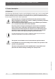
Pneumatic High-Speed Pressure Controller CPC3000 This Warning symbol indicates that danger of injury for persons and the environment and/or considerable material damage (mortal danger, danger of injury) will occur if the respective safety precautions are not taken. Warning This Caution symbol indicates danger for the system and material if the respective safety precautions are not taken. Caution This Notice symbol does not indicate safety notices but information for a better understanding of the facts.
Pneumatic High-Speed Pressure Controller CPC3000 11498171.01 08/2009 GB Contents 1. General notices 5 1.1 FCC Radio frequency emission notice 6 1.2 Software license agreement 6 1.3 Accreditations 6 1.4 Packaging for Shipment 7 2. Safety notices 7 2.1 User Responsibilities 7 2.2 General safety notices 7 2.3 Safety notices regarding operation 8 3. Product description 10 3.1 Proper use 10 3.2 Features 11 3.3 Turning on the CPC3000 12 3.4 Front panel 12 3.
Pneumatic High-Speed Pressure Controller CPC3000 SETUP Menus 31 7.8.1 SETUP Display 32 7.8.2 SETUP Control 33 7.8.3 SETUP Remote 34 7.8.4 SETUP Info 35 7.8.5 SETUP Service 36 8. Remote Operation 40 8.1 Remote SETUP 40 8.2 Remote SETUP - Ethernet 41 8.3 Remote SETUP - USB 41 8.4 Remote SETUP - IEEE-488 42 8.5 Remote Command Set 42 8.5.1 Mensor Command Set 43 8.5.2 PCS 400 Commands Emulated 48 8.5.3 PCS 200 Commands Emulated 50 8.5.
Pneumatic High-Speed Pressure Controller CPC3000 1. General notices In the following chapters detailed information on the pneumatic high-speed pressure controller model CPC3000 and its proper use can be found. Should you require further information, or should there be problems which are not dealt with in detail in the manual, please contact the following address: WIKA Alexander Wiegand SE & Co. KG Alexander Wiegand Strasse D-63911 Klingenberg Tel.
Pneumatic High-Speed Pressure Controller CPC3000 1.1 FCC Radio frequency emission notice This equipment has been tested and found to comply with the limits for a Class A digital device, pursuant to Part 15 of the FCC Rules. These limits are designed to provide reasonable protection against harmful interference when the equipment is operated in a commercial environment.
Pneumatic High-Speed Pressure Controller CPC3000 1.4 Packaging for Shipment If the product must be shipped to a different location or returned to WIKA for any reason through a common carrier it must be packaged properly to minimize the risk of damage. The recommended method of packing is to place the instrument in a container, surrounded on all sides with at least 10 cm of shock attenuation material such as styrofoam peanuts. 2. Safety notices 2.
Pneumatic High-Speed Pressure Controller CPC3000 Extreme care must be taken with pressure connections when using hazardous or toxic media. Warning Repairs must only be performed by authorized service personnel. Additional safety notices are found throughout this manual. 2.3 Safety notices regarding operation Warning HIGH PRESSURE! High pressure gases are potentially hazardous. Energy stored in these gases can be released suddenly and with extreme force.
Pneumatic High-Speed Pressure Controller CPC3000 Before pressurizing, the user must ensure through appropriate protective measures that the system or the device will not be overpressurized. When working with or on an instrument, safety glasses should be worn. Warning In areas where the system is operated there must be sufficient air ventilation due to inert gases that will escape during use. High pressure can accelerate parts in a manner that could be hazardous and cause physical injury. 11498171.
Pneumatic High-Speed Pressure Controller CPC3000 3. Product description 3.1 Proper use The Pneumatic High-Speed Controller model CPC3000 is a bench top or rack mounted Digital Pressure Calibrator/Controller used for test and calibration of mechanical pressure gauges, pressure switches, sensors, transducers, transmitters and any pressure related devices where time to set point is the most critical requirement. Warning Only dry clean air or nitrogen should be used as the pressure medium.
Pneumatic High-Speed Pressure Controller CPC3000 3.2 Features 1. The CPC3000 will control (up scale or down scale) into a 150 ml volume, to within 0.025 % of the set point, in 3 seconds or less. 2. Accuracy of 0.025 % FS, one year calibration interval. 3. Lightweight compact case with bezel and handle or 19" rack mount kit. 4. Manual operation via the color touch screen and easy access to auxiliary screens allow quick changes to the set point using the "STEP" and "JOG" screens. 5.
Pneumatic High-Speed Pressure Controller CPC3000 3.3 Turning on the CPC3000 The power switch is located on the rear of the instrument as shown in "Figure - Rear Panel". Power Switch Figure - Rear Panel 3.4 Front panel Figure - Front Panel 12 WIKA Operating Instruction Pneumatic High-Speed Pressure Controller ∙ Version 1.1 11498171.01 08/2009 GB The CPC3000 front panel (see above: "Figure - Front panel") includes a 7 inch colour SVGA display featuring touch screen technology.
Pneumatic High-Speed Pressure Controller CPC3000 3.5 Main menu When the CPC3000 is powered up it takes about one minute for initialization, then displays a screen similar to the "Figure - Initial Screen" below.
Pneumatic High-Speed Pressure Controller CPC3000 3.6 Front panel variations and navigation Bar Graph: The bar graph shows the relative indication of the range of the internal sensor, the user defined limits on the internal sensor, the unused portion of the internal pressure sensor range, the setpoint and the magnitude of the actual controlled pressure. The user defined control limits can be selected in the MAIN -> [SETUP] -> CONTROL SCREEN and can be set to correspond to the range of the device under test.
Pneumatic High-Speed Pressure Controller CPC3000 Optional elements can be chosen in the [SETUP-DISPLAY] screen explained in chapter 7.8.1 of this manual. Each optional element is displayed in the area below the pressure units. Area for optional elements Communication status Optional barometric reference display Figure - Optional Display elements Navigation to the SETUP screens is achieved pressing the Icon. SETUP "Figure SETUP Display Screen" shows the SETUP screen with the display table activated.
Pneumatic High-Speed Pressure Controller CPC3000 3.7 Main menu setpoint entry options Pressure setpoint entry options are chosen using the tab keys . "Figure - Numeric Keypad" shows the main menu with the numeric keypad selected. Figure - Numeric Keypad "Figure - STEP Keypad" shows the main menu with the STEP keypad selected. Figure - STEP Keypad Figure - JOG Keypad 16 WIKA Operating Instruction Pneumatic High-Speed Pressure Controller ∙ Version 1.1 11498171.
Pneumatic High-Speed Pressure Controller CPC3000 4. Specifications Specifications Pressure ranges CPC3000 bar Pressure types -1 ... +70 (depending on sensor) Absolute, gauge or bi-directional ranges Precision % FS < 0.015 Accuracy % FS < 0.025 Pressure units 33 selectable and 2 freely definable Control stability % FS < 0.004 Slew rate sec. < 3 (with a sudden pressure increase of 10 % FS in a 150 ml test volume) Control range % FS 0 up to 100 Test volume ccm 50 ...
Pneumatic High-Speed Pressure Controller CPC3000 5. Installation 5.1 Introduction The initial installation of the CPC3000 includes the following steps: Unpack the system, place it in a suitable workspace, connect it, switch it on and configure. 5.2 Unpacking the system Unpack all components of the CPC3000 carefully and check the parts for damage. Report any damage immediately to the forwarding agent.
Pneumatic High-Speed Pressure Controller CPC3000 5.4 Installation of the system The installation site must meet the following conditions: Operating Temperature: 10 to 50 °C Humidity: 0 to 95 % relative humidity non-condensation Flat, horizontal location; secure fixed working surface (desk top model) or installation in a 19" rack mount. At the back of the instrument sufficient air circulation must be provided for to avoid an accumulation of the heat conducted to the outside via the fan.
Pneumatic High-Speed Pressure Controller CPC3000 5.5 Rear panel Four pneumatic pressure ports are located on the rear panel (see below: "Figure - Rear panel"). Positioned on the left are the ethernet and RS-232 and GPIB connector, the off/on switch, the line fuses, and a protective grill covering the ventilating fan. Supply Port Fan Measure/Control Port Ethernet USB Reference Port Vent Mains input socket Exhaust/Vacuum Port Micro fuse Power supply IEEE-488.2 Figure - Rear panel 5.
Pneumatic High-Speed Pressure Controller CPC3000 5.7 Function of pressure connections MEASURE/CONTROL port Below the label "MEASURE/CONTROL" is a pressure connection. In MEASURE mode this connection connects the pressure applied to the internal sensor where the pressure is measured (within the range of the internal sensor). In CONTROL mode this connection supplies an output pressure controlled by the internal regulator at the commanded setpoint.
Pneumatic High-Speed Pressure Controller CPC3000 5.8 Electrical connections The electrical installation has to be carried out according to the following instructions while observing the relevant regulations. It is to be carried out by a qualified electrician. Warning 5.8.1 Connecting the power supply and turning on the instrument Before connecting the power supply, make sure that the mains voltage agrees with the specification of the power unit.
Pneumatic High-Speed Pressure Controller CPC3000 Please consult your Computer Resources Department prior to connecting this instrument to your network to verify there are no conflicts with existing IP addresses. Warning Ethernet communications are transmitted over a standard RJ-45 cable. Prior to first time use of ethernet communication, the four parameters "IP", "Netmask", "Gateway" and "Port" must be SETUP. These are configured in the communications SETUP screen. 6.
Pneumatic High-Speed Pressure Controller CPC3000 7. Operation via Touch-screen This chapter describes the procedures for operating the CPC3000 from the front panel. Tabs, Keys, Value Entry and Check Boxes: Local operation is accomplished by observing the data presented in the display menus, then pressing the on-screen tab, key, value entry or check box for the desired sub-menu, function or selection.
Pneumatic High-Speed Pressure Controller CPC3000 User defined DUT / control range limits (configurable via SETUP) SETUP menu Setpoint Stable indication Numeric keypad Current pressure value Pressure mode indication Pressure unit key - Delete selected set point Bar graph - Delete last entered digit - Accept selected set point MEASURE CONTROL VENT Measure mode pneumatically connects the pressure sensor directly to the device under test. In measure mode pressure regulation is inactive.
Pneumatic High-Speed Pressure Controller CPC3000 7.3 Setpoint Entry The control setpoint can be entered using the default numeric keypad or the alternate STEP or JOG keypads that appear on the right side of the main menu when selected using the [setpoint entry side-menu] tabs on the lower right hand side of the main menu. These alternative methods of entering the setpoint have advantages in different situations and have been designed to increase ease of use and productivity.
Pneumatic High-Speed Pressure Controller CPC3000 7.4 Operating modes The selection keys for the operating modes MEASURE, CONTROL and VENT are located at the bottom of the main menu. [MEASURE]: In MEASURE mode, the instrument measures the pressure connected to the MEASURE/ CONTROL port. "Figure - MEASURE Mode" shows the state of the isolation valves in MEASURE mode. When the CPC3000 is turned off all the valves close and could trap pressurized gas within the pneumatics.
Pneumatic High-Speed Pressure Controller CPC3000 [CONTROL]: In CONTROL mode the instrument provides a precise pressure output (equal to the setpoint +/- the stability specification) at the MEASURE/CONTROL port. The indication of the current pressure value will turn green when the setpoint has been reached and the stable window settings have been satisfied. "Figure - CONTROL Mode" shows the state of the isolation valves in measure mode. Notice that the regulator is active in the CONTROL mode.
Pneumatic High-Speed Pressure Controller CPC3000 [VENT]: VENT mode vents the pneumatic system and shuts off the supply. "Figure - VENT mode" shows the state of the isolation valves in VENT mode. VENT Mode SUPPLY VENT Optional barometric reference Optional barometric sensor Regulator is inactive Pressure transducer EXHAUST / VACUUM Valve is open MEASURE / CONTROL REFERENCE Valve is closed 11498171.
Pneumatic High-Speed Pressure Controller CPC3000 7.5 Data Entry When there is a requirement to enter specific numeric or alpha values into the system, the method of entry is consistent for all instances. When a [VALUE ENTRY] key is pressed a dialog box will appear similar to "Figure - Value Entry". This Value Entry dialog box will have a numeric or alpha keypad, when appropriate minimum and maximum value limits, current value and a window that shows the new value entered.
Pneumatic High-Speed Pressure Controller CPC3000 A gray background on a [Pressure Units] key indicates that it is the current selection. Touch any other [Pressure Units] key, and press [back] key to enable change and return to previous operation screen. All of the displayed pressure values will have changed to correspond to the newly selected units. 7.
Pneumatic High-Speed Pressure Controller CPC3000 7.8.1 SETUP Display The MAIN -> SETUP -> DISPLAY menu contains elements that change the appearance and function of components displayed on the main menu. Following is a description of the elements of this menu. Filter: The filter selection keys [Low], [Normal], and [high] dampen the pressure display to reduce the affect of pneumatic noise associated with the device under test or the test environment.
Pneumatic High-Speed Pressure Controller CPC3000 7.8.2 SETUP Control Configuration of parameters associated with setting limits and adjusting parameters used to control pressure are configured in the MAIN -> [SETUP] -> [CONTROL] menu shown in "Figure - SETUP Control". Figure - SETUP Control 11498171.
Pneumatic High-Speed Pressure Controller CPC3000 [Preset Points] allows the operator to select the number of points that appear as steps. For example: in "Figure - preset points" [5] is entered as the preset points value, this automatically configures 5 points from 0 to 100 % of user defined range. It automatically calculates the steps that populate the STEP keypad in the main menu. Figure - Preset Points 7.8.
Pneumatic High-Speed Pressure Controller CPC3000 The USB SETUP key opens a dialog box where baud rate (9600, 19200, 38400, 57600, or 115200), data bit (7 or 6), stop bit (1 or 2), parity (none, odd or even) can be chosen. There is also a check box that turns echo on (checked) or off (unchecked). The IEEE address data entry button when pressed will open a data entry dialog box where the IEEE address can be entered. In the Communication section there are three remote command set emulation settings.
Pneumatic High-Speed Pressure Controller CPC3000 7.8.5 SETUP Service The SETUP service screen is a password protected area where calibration of the sensor and SETUP of the regulator is acomplished. Figure - SETUP Service Figure - Zero 36 WIKA Operating Instruction Pneumatic High-Speed Pressure Controller ∙ Version 1.1 11498171.01 08/2009 GB The SETUP service screen allows zero adjustment without entering the password. A zero adjustment screen, "Figure - Zero", opens when the [ZERO] button is pressed.
Pneumatic High-Speed Pressure Controller CPC3000 To access the password protected portion of the SETUP service screen press the key. This opens a password entry screen, "Figure - Password", where the password can be entered. Entering the password will open the SETUP service screen, "Figure - SETUP Service Unlocked", and allow access to all the SETUP options. Figure - Password 11498171.
Pneumatic High-Speed Pressure Controller CPC3000 After the password has been entered the SETUP Service screen allows access to the Calibrate, Seal Point, Linerize, and Adaptation screens. Consult factory before changing any Seal Point, Linerization or Adaptation parameters. Warning Press the [CALIBRATE] key to access the calibrate screen, "Figure - Calibrate Data". Figure - Calibrate Data The Calibrate screen contains three tabs: DATA, EDIT AND CALIBRATE.
Pneumatic High-Speed Pressure Controller CPC3000 Figure - Calibrate Edit 11498171.01 08/2009 GB The Screen accessed by pressing the [CALIBRATE] tab, "Figure - Calibrate Calibrate", allows the operator to perform a live calibration while connected directly to a primary standard. In this mode, the CPC3000 will display the currently measured pressure in the Actual column when the measured pressure is within a few percent of the value in the Desired column.
Pneumatic High-Speed Pressure Controller CPC3000 8. Remote Operation When the instrument is turned on, BIOS routines test the system CPU board. These tests may take up to 60 seconds. After the BIOS tests, LINUX is loaded. LINUX will then call the executable file. The executable file will go through a series of software and hardware initialization. The following hardware/software is initialised: 8.
Pneumatic High-Speed Pressure Controller CPC3000 8.2 Remote SETUP – Ethernet The Ethernet communication port allows the CPC3000 to communicate with computers using 10/100 Bases-T specification. Ethernet communications are transmitted over a standard RJ-45 cable. Connecting directly to a PC requires a crossover Ethernet cable. Hub or router connections require a straight Ethernet cable. Before using Ethernet communication, four parameters must be set up: IP, Netmask, Gateway and Port.
Pneumatic High-Speed Pressure Controller CPC3000 8.4 Remote SETUP – IEEE-488 The IEEE-488 communication port allows the CPC3000 to communicate with computers using an IEEE-488 cable. This screen, "Figure - IEEE-488 Address", is accessed by pressing the IEEE-488 numeric value box in the SETUP Remote screen. After pressing the numeric value box a number entry keypad will appear for entering the new IEEE-488 address.
Pneumatic High-Speed Pressure Controller CPC3000 8.5.1 Mensor Command Set Command Data Response/Function ? See Table Below Returns data per the current output format. Acquire? 15 char string. Ex: Acquire? Test_stand_1 This command is used when multiple computers would like to control the instrument. Yes if acquisition is successful, No if instrument is being controlled with another computer.
Pneumatic High-Speed Pressure Controller CPC3000 Command Data Response/Function Decpt? n Returns the number of decimal points for the active channel. (see Resolution) Default None Sets the default values. DHCP Reserved for DHCP SETUP DHCP? Reserved for DHCP SETUP Integer DIO? 2 turns on digital output, 0 turns it off. Bit0 = input, bit1 = output DOC mm/dd/yyyy Sets the date of cal for the active sensor and turndown.
11498171.01 08/2009 GB Pneumatic High-Speed Pressure Controller CPC3000 Command Data Response/Function IP? nnn.nnn.nnn.nnn Returns the IP address of the instrument. Keylock Yes or No Locks or unlocks keyboard. Keylock? (Yes or No) Returns Yes or No. List? Pri,X,X;Sec,X,X;Bar,1 Returns list of available turn-downs on installed sensors in the active channel. X will be non-existent if the turndown isn’t available.
Command Data Response/Function Rdecpt? n Returns the number of rate decimal points for the active channel. (see Resolution) Release? 15 char string. Ex: Release? Test_stand_1 This command is used to release control of the instrument in a multiple computer environment. Yes if release is successful. No if instrument is being controlled with another computer.
11498171.01 08/2009 GB Pneumatic High-Speed Pressure Controller CPC3000 Command Data Response/Function Span desired pressure or ? Sets span on active transducer or for ?, clears previous value, must be > 50 %FS and has a 1 % limit. Span? XXXXXXX Returns span scale factor for active transducer. Sparity Even, Odd, None Sets the serial parity. Sparity? CCCC Returns the serial parity. Sstop 1 or 2 Sets the serial stop bits.
Pneumatic High-Speed Pressure Controller CPC3000 Command Data Response/Function Vent None Instrument placed in Vent Mode. Vent? (Yes or No) Returns Yes if instrument is in Vent, No if otherwise. Window Value in current units Sets the exponential filter window for the active sensor. Window? n.nnnnne+nn Returns the exponential filter window for the active sensor. Zero desired pressure or ? Sets zero to set pressure or for ?, clears previous value.
Pneumatic High-Speed Pressure Controller CPC3000 11498171.01 08/2009 GB Command Data Response/Function _psc4 filtersetting Sets the filter %. _pcs4 filtersetting? Returns the filter %. _pcs4 filterwindow Sets the filter window. _pcs4 filterwindow? Returns the filter window. _pcs4 func ctrl Instrument placed in control mode at pressure in units. _pcs4 func emul Toggles ptype emulation mode. _pcs4 func F1 Toggles ptype emulation mode.
Pneumatic High-Speed Pressure Controller CPC3000 Command Data Response/Function _pcs4 stabledelay? Returns the number of readings that must be within the stable window before a stable pressure is indicated. _pcs4 stablewindow Sets the pressure window that is used to indicate pressure is stable. _pcs4 stablewindow? Returns the pressure tolerance allowed for a stable pressure indication as a % of span of the active transducer.
Pneumatic High-Speed Pressure Controller CPC3000 11498171.
Pneumatic High-Speed Pressure Controller CPC3000 8.5.
Pneumatic High-Speed Pressure Controller CPC3000 Command Data Response/Function *ESE? Returns enable status event value *ESR Event status register *ESR? Returns event status register value *SRE Service request enable *SRE? Returns service request enable value *STB? Returns status byte 8.5.6 SCPI Commands Notes: 1. if Wika option is enabled, SCPI units are BAR, otherwise SCPI units are the currently selected unit.
Pneumatic High-Speed Pressure Controller CPC3000 Command Response/Function :UNIT [:NAME]? Returns ASCII units (mixed case) :VALue? Returns the units conversion factor :REFerence [:HEIGht] Sets the head pressure height :MODE? Returns “OFF”, “GAS”, or “LIQUID” :MODE OFF | GAS | LIQUID Sets the head pressure mode :MEDium Sets the medium density SYSTem :DATE Sets sytem date YY,MM,DD :TIME Sets system time HH,MM,SS :ERRor[:NEXT]? R
Pneumatic High-Speed Pressure Controller CPC3000 Command Response/Function CALCulate :LIMit :LOWer Set the minimum control limit :LOWer? Set the minimum control limit :UPPer Set the maximum control limit :UPPer? Set the maximum control limit :SYSTem :DETECT SLOW | FAST | CANCEL Control autotune (NOT USED NOW) :DETECT? Returns state of control autotune 11498171.01 08/2009 GB Output formats 1. pressure value 2.
Pneumatic High-Speed Pressure Controller CPC3000 9. Trouble-shooting measures If faults cannot be repaired, the system must be taken out of operation immediately and protected against unintentional restarting. This information should be reported to authorized service personnel. Warning Repairs must only be performed by the manufacturer or authorized service personnel.
Pneumatic High-Speed Pressure Controller CPC3000 Type of fault Measures V. The set value is not reached. Check whether the value of the supply pressure at the SUPPLY HIGH port is the value required and leak-test the pipe connections. If the fuses of the power supply input socket have to be replaced, use 1.5 A, 230 V AC only. Warning If you require further help please contact the WIKA department of Testing and Calibration Technology under: 11498171.
Pneumatic High-Speed Pressure Controller CPC3000 10. Re-calibrating and servicing We recommend having the system re-calibrated by the manufacturer at regular intervals of approximately 12 months. Every re-calibration at the factory also includes a comprehensive and free checking of all system parameters. The CPC3000 requires almost no maintenance, because all moving parts are extremely robust. There are no parts which have to be serviced by the user.
Pneumatic High-Speed Pressure Controller CPC3000 11. Removal of the system Work on electrical or pneumatic/hydraulic equipment must only be carried out by qualified and authorized service personnel, observing the corresponding safety regulations. Warning When dismantling the system proceed as follows: 1. Make sure that there is no positive or negative pressure on the system and that all parts of the instrument are at room temperature. 2.
Pneumatic High-Speed Pressure Controller CPC3000 12. Transport of the system Before the system is shipped it must be clean and free of dirt and debris. This is particularly important if the medium is a health hazard such as a corrosive, toxic, carcinogenic, radioactive, etc. Warning The precision measuring system CPC3000 must only be shipped in an appropriate transport box. If necessary, please ask for a proper transport box: Phone Fax.
Pneumatic High-Speed Pressure Controller CPC3000 13. Storage of the system Before the system is stored it must be clean and free of dirt and debris. This is particularly important if the medium is a health hazard such as a corrosive, toxic, carcinogenic, radioactive, etc.
Pneumatic High-Speed Pressure Controller CPC3000 14. Placing out of service Before the system is shipped it must be clean and free of dirt and debris. This is particularly important if the medium is a health hazard such as a corrosive, toxic, carcinogenic, radioactive, etc. Warning When placing the system out of service, please dismantle it according to the instructions in the manual in chapter "11. Removal of the system". 11498171.
Pneumatic High-Speed Pressure Controller CPC3000 15. Appendix 11498171.01 08/2009 GB Sales and Service International Table – Measurement Units Table – Conversion Factors, Pascal WIKA Operating Instruction Pneumatic High-Speed Pressure Controller ∙ Version 1.
Pneumatic High-Speed Pressure Controller CPC3000 MEASUREMENT UNITS The Units command selects the measurement units to be output on the bus and the display.
Pneumatic High-Speed Pressure Controller CPC3000 CONVERSION FACTORS, PASCAL The following table lists factors which should be used as multipliers when converting other pressure units to or from Pascal. 11498171.01 08/2009 GB Table – Conversion Factors, Pascal Unit No.
Pneumatic High-Speed Pressure Controller CPC3000 11498171.01 08/2009 GB FOR YOUR NOTES 66 WIKA Operating Instruction Pneumatic High-Speed Pressure Controller ∙ Version 1.
Pneumatic High-Speed Pressure Controller CPC3000 11498171.01 08/2009 GB FOR YOUR NOTES WIKA Operating Instruction Pneumatic High-Speed Pressure Controller ∙ Version 1.
Pneumatic High-Speed Pressure Controller CPC3000 WIKA worldwide North America Romania Austria WIKA Instruments Romania WIKA Messgerätevertrieb Ursula Wiegand GmbH & Co. KG S.R.L. Bucuresti, Sector 5 1230 Vienna Calea Rahovei Nr. 266-268 Tel. (+43) 1 86916-31 Corp 61, Etaj 1 Fax: (+43) 1 86916-34 Tel. (+40) 21 4048327 E-mail: info@wika.at Fax: (+40) 21 4563137 www.wika.at E-mail: m.anghel@wika.ro Benelux Russia WIKA Benelux ZAO WIKA MERA 6101 WX Echt 127015 Moscow Tel. (+31) 475 535-500 Tel.