Operating Instructions Automated Pressure Calibrator CPC 6000 Automated Pressure Calibrator CPC 6000 PN 0017222001T
Automated Pressure Calibrator CPC 6000 ! Warning ! This Warning symbol indicates that danger of injury for persons and the environment and/or considerable material damage (mortal danger, danger of injury) will occur if the respective safety preccautions are not taken. This Caution Symbol indicates danger for the system and material if the respective safety precautions are not taken. Caution i This Notice Symbol does not indicate safety notices but information for a better understanding of the facts.
Automated Pressure Calibrator CPC 6000 TABLE OF CONTENTS Page 1. General Information 7 1.1 Warranty 1.2 Important Notice 1.3 Compliance 1.4 Trademarks and Copyrights (C) 1.5 Software License Agreement 1.6 Mensor Service Plus 1.6.1 After the Warranty 1.6.2 Calibration Services 1.6.3 Accreditations 1.7 Packaging for Shipment 7 7 7 8 8 8 8 9 9 9 2. Safety Notices 11 2.1 User Responsibilities 2.2. General Safety Notices 2.3 Warnings and Caution Notices 11 11 12 3. Product Description 13 3.
Automated Pressure Calibrator CPC 6000 6. Local Operation 29 6.1 General 6.2 Keys and Tabs 6.3 Display Screen Features 6.3.1 [Mensor] Logo 6.3.2 [Flag] Symbol 6.3.3 [>] and [<] Keys 6.3.4 Turndown Label and [Range Selector] Key 6.3.5 Pressure Label 6.3.6 Pressure [Units] Key 6.3.7 [Step Value] Key 6.3.8 Step Down [] and Step Up [] Keys 6.3.9 Control Pressure [Setpoint Value] 6.4 [Program] Key 6.4.1 Editing or Creating a Program 6.4.2 Running a Program 6.5 [Local] Label 6.6 [Setup] Key 6.6.
Automated Pressure Calibrator CPC 6000 7.4.7.3.1 Output Formats 7.4.7.3.2 Error Messages and Error Codes 7.4.7.4 DPI 510 Emulation Commands 65 65 66 8. Options 71 8.1 Transport Case (PN 0011159001) 8.2 Rack Mount Kit 8.3 Calibration Sled Kit 8.4 Additional Transducers 8.4.1 Secondary Transducer Installation 8.5 Barometric Reference Transducer 8.5.1 Gauge Pressure Emulation Key 8.5.2 Absolute Pressure Emulation Key 8.5.3 Calibration 8.5.4 Specifications 8.6 Virtual Delta Channel 8.6.1 Delta Functions 8.
Automated Pressure Calibrator CPC 6000 10.3 Pressure Standards 10.4 Media 10.5 Calibration Setup 10.6 Password 10.6.1 Change Password 10.7 Restoring a Mensor Calibration 10.8 On-site Calibration 10.8.1 CPC 6000 Preparation Procedure 10.8.2 [Calibrate] Setup Key 10.8.3 1-Point Calibration 10.8.4 2-Point Calibration 10.9 Head Pressure Correction 89 89 89 91 91 93 93 93 93 95 96 97 11. Appendix 99 11.1 Measurement Units 11.2 Conversion Factors, PSI 11.3 Conversion Factors, Millitorr 11.
Automated Pressure Calibrator CPC 6000 1. General Information 1.1 Warranty All products manufactured by Mensor® Corporation (Mensor) are warranted to be free of defects in workmanship and materials for a period of one year from the date of shipment. No other express warranty is given, and no affirmation of Seller, by words or actions, shall constitute a warranty. SELLER DISCLAIMS ANY IMPLIED WARRANTIES OF MERCHANTABILITY OR FITNESS FOR ANY PARTICULAR PURPOSES WHATSOEVER.
Automated Pressure Calibrator CPC 6000 These directives are designed to provide reasonable protection against harmful interference when the equipment is operated in a commercial environment. This equipment generates, uses, and can radiate radio frequency energy and, if not installed and used in accordance with the instruction manual, may cause harmful interference to radio communications.
Automated Pressure Calibrator CPC 6000 1.6.2 Calibration Services In addition to servicing our own products, Mensor provides complete pressure calibration services up to 20,000 psi for many pressure instruments. This service includes a Certificate of Compliance and Calibration and a record of traceability to the pressure standards of the United States National Institute of Standards and Technology (NIST). 1.6.3 Accreditations Mensor Corporation is registered to ISO 9001:2008.
Automated Pressure Calibrator CPC 6000 NOTES 10 Mensor/WIKA Operating Instructions - CPC 6000
Automated Pressure Calibrator CPC 6000 2. Safety Notices 2.1 User Responsibilities To ensure safety, the user must make sure that: ■ The system is used properly, no dangerous media are used and that all technical specifications are observed. ■ The system is operated in perfect operating condition. ■ This operation manual is legible and accessible to the user at the system’s location. ■ The system is operated, serviced and repaired only by authorized and qualified personnel.
Automated Pressure Calibrator CPC 6000 2.3 Warnings and Caution Notices ! WARNING: HIGH PRESSURE! High pressure gases are potentially hazardous. Energy stored in these gases can be released suddenly and with extreme force. High pressure systems should be assembled and operated only by personnel who have been trained in proper safety practices.
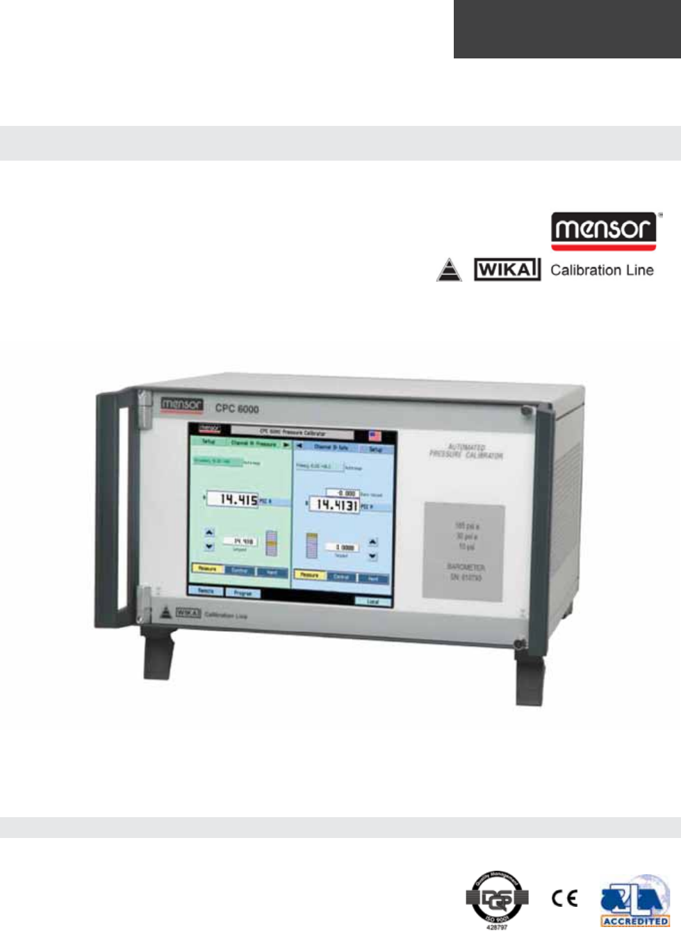
Automated Pressure Calibrator CPC 6000 3. Product Description 3.1 General Description The Mensor CPC 6000 Automated Pressure Calibrator is a multi-channel/multi-range pressure system designed to test and calibrate a variety of pressure devices in either absolute or gauge pressure modes. The CPC 6000 can have two independent control channels each with its own pressure regulator. Each control channel can have up to two transducers.
Automated Pressure Calibrator CPC 6000 3.2 Features Here is a short list of significant features designed into the CPC 6000: 1. 0.01%Intelliscale-50 Uncertainty. 2. Up to four (two per channel) highly stable, temperature compensated, pressure transducers. 3. An optional internal high accuracy barometric reference transducer provides gauge pressure emulation for all of the absolute ranges and absolute pressure emulation for gauge ranges; 4.
Automated Pressure Calibrator CPC 6000 3.4 Display When the CPC 6000 is powered up it takes about one minute for initialization, then displays a screen similar to Figure 3.4. The display is made up of rectangles which display text or symbols. Figure 3.4 - Terminology of Screen Elements Keys, Tabs, Labels or Windows: In this manual a key is a small rectangle which acts as a switch when pressed. Keys have borders with a three dimensional, shadowed effect.
Automated Pressure Calibrator CPC 6000 Optional Display: The optional display is a window near the pressure label. This window can be set up to be blank, or to display any one of the following: ■ Peak Pressure – minimum and maximum ■ Rate of change of a measured pressure ■ Barometer reading Footer Keys: Like the top bar, the [Remote] and [Program] keys on the bottom left corner of the display remain permanently on-screen. Touching either of these keys will cause that subject page to appear in the display.
Automated Pressure Calibrator CPC 6000 3.5 Electrical Module The electrical module is illustrated below with the instrument lid removed (Figure 3.5). All program information to run the system resides on a solid state disk module located on this module. The power switch and line fuses are situated on the rear of the electrical module such that they are accessible on the rear of the fully assembled CPC 6000. Figure 3.
Automated Pressure Calibrator CPC 6000 3.6 Pneumatic Module Pneumatic modules come in two types and are referred to in this manual as the “Pump Regulator” or the “Solenoid Valve Regulator”. The pump regulator is used with low pressure sensors specified in Section 4, Specifications.
Automated Pressure Calibrator CPC 6000 3.7 Chassis Assembly The chassis assembly acts as the housing for the system. The electrical and pneumatic modules are each self-contained inside the chassis, and either can be replaced using basic hand tools. In addition, each pressure transducer is individually removable without tools. Instructions for transducer and module removal are provided in Section 9, Maintenance.
Automated Pressure Calibrator CPC 6000 3.8 Electrical Block Diagram Figure 3.
Automated Pressure Calibrator CPC 6000 4. Specifications Accuracy specifications presented herein are obtained by comparison with primary standards traceable to the National Institute of Standards and Technology (NIST). These specifications are obtained in accordance with the ISO Guide to the Expression of Uncertainty in Measurement (GUM). Any exception are noted on the individual calibration certificate. Mensor reserves the right to change these specifications without notice. 4.
Automated Pressure Calibrator CPC 6000 Pressure Ranges Specific ranges within the range intervals are selected by the customer. Optional Barometer Range 11 to 17 psia Optional Barometer Uncertainty 0.
Automated Pressure Calibrator CPC 6000 Control Time Fast Mode: 10 seconds to stable flag for 10% FS step pressure change into a 50cc volume. Larger volumes can lengthen this time. Controlling to low absolute pressures will lengthen this time. Slow Mode: 15 seconds to stable flag for 10% FS step pressure change into a 50cc volume. Larger volumes can lengthen this time. Controlling to pressures less than 0.5 psia will lengthen this time. Supply Consumption Fast Mode: Zero after setpoint is reached.
Automated Pressure Calibrator CPC 6000 4.4 General Specifications Size 14.02” wide x 7.55” high x 12.42” deep (35.61 cm x 19.2 cm x 31.55 cm). See Figure 5.2. Weight 36 lbs. (16.33 kg) with all internal options. Power Input Requirements 100-240 VAC, 47-63 Hz, 75 VA max. Fuses: 1.5A, 230V, Type T LITTLEFUSE 31301.5 Digital I/O Pin 1: +5 VDC, 100 mA max. Pin 2: Input TTL levels. Voltage input should be limited to > -0.3 VDC and < +5.3 VDC. Pin 3: Output pulled up to 5 VDC with a 10k ohm resistor.
Automated Pressure Calibrator CPC 6000 5. Installation 5.1 Unpacking the System In addition to this manual you should have: ■ ■ ■ ■ ■ CPC 6000 Automated Pressure Calibrator Power cord 1/8 inch FNPT fitting adapters fastened to rear panel Any accessories ordered An envelope containing the Calibration Certificate Your new instrument was subjected to many hours of functional testing before it left the factory.
Automated Pressure Calibrator CPC 6000 5.4 Rear Panel Up to eight pneumatic pressure ports are located horizontally across the rear panel (Figure 5.4). Positioned to the right of the pressure ports are the Ethernet, RS-232 and GPIB connector, the off/on switch, the line fuses, and a protective grill covering the ventilating fan. Figure 5.4 shows a rear panel containing two solenoid valve regulator pneumatic modules. Rear panels may differ depending on what modules are installed. Figure 5.
Automated Pressure Calibrator CPC 6000 5.5 Pressure Connections i When making up a connection to an o-ring adapter port use a back-up wrench to prevent over-stressing the threads in the manifold block. Notice All of the pressure ports on the rear are female 7/16 - 20 SAE/MS straight threads per MS16142 and SAE J514 table 14. They require a tube fitting boss seal with an o-ring per MS33656. Mensor provides female 1/8” NPT adapter fittings with the instrument.
Automated Pressure Calibrator CPC 6000 5.5.3 Exhaust Port If sub-atmospheric control pressure is required a vacuum pump must be connected to the EXHAUST port. Otherwise, this port may be left open to atmosphere. 5.5.4 Reference Port On gauge units this port is connected to the reference side of the transducer, and on absolute units it is internally capped. This port is normally left open to atmosphere but may be attached to a snubber assembly on very low pressure instruments. 5.5.
Automated Pressure Calibrator CPC 6000 6. Local Operation 6.1 General This section describes the procedures for operating the CPC 6000 from the front panel. Instructions for operating the device remotely from an external computer are covered in the next section, Remote operation. By following the procedures provided in these two sections and the Calibration section, you can expect your CPC 6000 to deliver maximum accuracy and dependability for many years of useful service. 6.
Automated Pressure Calibrator CPC 6000 Figure 6.3B is an example of a typical display after initialization. To expand the selected channel to a single channel operation screen as shown in Figure 6.3A, press the [>] key. The [Standby] key appears on the screen when expanded. To expand or return to a dual channel operation screen press the [<] or [>] key. Figure 6.3B - Typical Operation Screen All of the CPC 6000 screen features are described in more detail in the rest of this section. 6.3.
Automated Pressure Calibrator CPC 6000 The current language selections available are: Language Country English USA German Germany German Switzerland English Great Britain Chinese China English Canada French France French Switzerland English Ireland Korean Korea French Canada Italian Italy Russian Russia Polish Poland Japanese Japan Spanish Mexico Spanish Spain Figure 6.3.
Automated Pressure Calibrator CPC 6000 i Some pressure units can cause a number to be too long for the value window. In those cases the value will be abbreviated with an “m” (milli), “k” (kilo), or “M” (mega) multiplier appended to the range in the range drop list. Notice An important feature of the CPC 6000 is that transducers can easily be changed. A transducer can be replaced in the CPC 6000 in less than 30 seconds, with no tools required.
Automated Pressure Calibrator CPC 6000 The current units are highlighted by a yellow background. Touch any other [Pressure Units] key, and press [OK] to enable change and return to previous operation screen. All of the displayed pressure values will have changed to correspond to the newly selected units at the correct conversion ratio. Figure 6.3.6 - Units Selection Window 6.3.7 [Step Value] Key On the left side of the screen as seen in Figure 6.3A is the [Step Value] key. The step value displayed is 0.
Automated Pressure Calibrator CPC 6000 6.3.8 Step Down [] and Step Up [] Keys As shown in Figure 6.3A, the [] and [] keys are located to the side (different for A and B Channels) of the [Setpoint Value] key; one for Step Down [], and another for Step Up []. Pressing an arrow key will change the setpoint by the step value until the control limits of the channel are reached. 6.3.
Automated Pressure Calibrator CPC 6000 6.4 [Program] Key The [Program] key on the bottom left of the operation screen (see Figure 6.3B) enters the main program creation/edit screen shown in Figure 6.4A. Programmed multi-step sequences can be entered and edited from this screen. There are sample programs available in the instrument that can be edited and renamed. A saved program can be executed by entering the setup channel screen and selecting the [Program] key.
Automated Pressure Calibrator CPC 6000 6.4.1 Editing or Creating a Program To edit or create a program, select a program name from the Program Selection Screen and press [OK]. This brings up the main program screen. Below the [Name] key is a table that shows a synopsis of the program steps. There are also up and down arrow keys to display additional pages of program steps. To edit the selected program press the [Edit] key. This displays the program editing screen shown in Figure 6.4.1A. Figure 6.4.
Automated Pressure Calibrator CPC 6000 To change the name of the program, press the [Name] key. This displays a keyboard screen shown in Figure 6.4.1B. Enter the name of the program and press [OK] to return to edit the program steps. Figure 6.4.1B - Keyboard Screen The Program Line Edit Screen (Figure 6.4.1C) sets the function of each program line. Each program line performs the function selected from the ones displayed in the left-most column. Figure 6.4.
Automated Pressure Calibrator CPC 6000 [Setpoint%] key: The [Setpoint%] key sets the control pressure at the entered percentage of the range of the currently active transducer. [Delay] key: The [Delay] key delays the execution of the program for the entered number of seconds.
Automated Pressure Calibrator CPC 6000 The [>] key begins execution of the program at the first program line. It is also used to re-start a program at the current line after a wait/pause program line. The next key shows a black square. Pressing this key stops execution of the program and resets the program to the first program line. The [II] key pauses program execution at the current program line. If the [>] key is subsequently pressed, the program begins execution at the next program line. 6.
Automated Pressure Calibrator CPC 6000 The content of the three active displays are: [Pressure]: Shows no alternate readings on the screen, only the measured pressure reading. [Peak]: Displays the highest and lowest pressure points since the last [Reset], or power up. Figure 6.3B shows an example of the Peak feature displayed in this window. [Rate]: Reports the rate at which the measured pressure is changing in units/second.
Automated Pressure Calibrator CPC 6000 6.6.2 [Sensor] Setup Touch the [Sensor] tab and Figure 6.6.2A will appear. Figure 6.6.2A - Sensor Setup Screen Filter: The Filter is an electronic filter to smooth out the pressure readings. Because of the differences in resolution, more filtering may display a more stable reading for some pressure units. Select the best filter for the current units. [Off], [Low], [Normal], [High].
Automated Pressure Calibrator CPC 6000 6.7 Pump Regulator Control Limits: The control limits cannot be set outside the maximum or minimum ranges of the transducers installed on the active channel. To change a limit touch either of the [Limit Value] keys and enter the new value. Figure 6.7.1A - Controller Setup, Pump Regulator Figure 6.7.
Automated Pressure Calibrator CPC 6000 Rate: A rate (slewing speed) which best suits the user’s test requirements is selected here. The [Slow] rate will use internal pressure generation without the use of the roughing supply and exhaust valves. Use this mode if no external supply or exhaust pressures are applied to the selected pressure control channel. The [Fast] rate utilizes the roughing supply and exhaust valves.
Automated Pressure Calibrator CPC 6000 Rate: A rate (slewing speed) which best suits the user’s test requirements are selected here. The rates vary the pressure slew rate while driving to a pressure setpoint. The [Slow] rate will target approximately .1% of the highest installed range/second. The [Medium] rate will target approximately 1% of the highest installed range/second. The [Fast] rate will target approximately 10% of the highest installed range/second.
Automated Pressure Calibrator CPC 6000 7. Remote Operation 7.1 Remote Setup Use the following screens to set the operating parameters for the Ethernet, RS-232 serial port, and IEEE-488. Press the [Remote] key located on the bottom left corner of the screen, and a new display appears with another set of tabs across the top as shown in Figure 7.1.1. 7.1.1 [Instrument] Setup Screen Press the [Instrument] tab to set up available emulation modes. The default command set is Mensor. Figure 7.1.
Automated Pressure Calibrator CPC 6000 7.1.2 [IEEE-488] Setup Screen Press the [IEEE-488] tab to set up the IEEE address. Press the white box and a number keypad will appear for you to enter your new IEEE address and then press [OK]. Figure 7.1.2 - [IEEE-488] Setup Screen 7.1.3 [Serial] Setup Screen Press the [Serial] tab to set up the serial port parameters. These parameters should be set up to match your host computer. Default settings are: 57600, 8,1, none parity, and no echo.
Automated Pressure Calibrator CPC 6000 7.1.4 [Ethernet] Setup Screen Press the [Ethernet] tab to set up the Ethernet parameters. These parameters should be set up to match your host computer. Figure 7.1.4 - [Ethernet] Setup Screen When the correct values have been selected for all four parameters simply touch any of the keys across the top or the bottom of the screen or the [X] key on the upper right of the window to move on to another function.
Automated Pressure Calibrator CPC 6000 7.3.1 Capability Codes SH1 Full source handshake capability AH1 Full acceptor handshake capability T6 Talker with serial poll and unaddress if MLA L4 Listener with unaddress if MTA SR1 Full service request capability RL1 Full remote/local capability including LLO PP0 No parallel poll capability DC1 Full device clear capability DT1 Full device trigger capability C0 No controller capability E2 Tri-state outputs 7.3.
Automated Pressure Calibrator CPC 6000 Figure 7.4.1 - Serial Cable 7.4.2 Command and Query Format Commands must be sent in ASCII format and terminated with either a carriage return (), linefeed () or both. Commands are not case sensitive. Each query returns a response. If an error is detected the response will include an error flag. One of the first commands issued when starting remote communications should be “Keylock Yes”.
Automated Pressure Calibrator CPC 6000 Always send commands in one of the following formats: 1. 2. 3. [Command] [Termination]; [Command] [Separator] [Data] [Termination]; Queries are special instructions in the form: [Command?] [Termination] where the question mark, “?”, immediately precedes the terminator. When a valid query is received, the CPC 6000 will return {data} terminated by CR and LF. Floating point data is returned in the current engineering units in exponential format. 7.4.
Automated Pressure Calibrator CPC 6000 7.4.5 Commands and Queries Table 7.4.5 lists all of the current CPC 6000 specific commands and queries. i Channel specific commands are sent to only the active channel. See ‘CHAN’ command. Notice Optional emulation modes are available in which the CPC 6000 can emulate remote functions of different brands of pressure controllers. Please contact Mensor for more details. Table 7.4.
Automated Pressure Calibrator CPC 6000 16 BR? {value} Returns the B channel rate. 17 BRS? {YES or NO} Returns the B channel rate stable flag. 18 BS? {YES or NO} Returns the B channel stable flag. 19 Caldisable {YES or NO} Disables the zero and span commands (default = YES). When the cal-disable is YES, the zero and span commands are disabled. 20 Caldisable? {YES or NO} Returns whether or not calibration of the active sensor is disabled.
Automated Pressure Calibrator CPC 6000 39 Errorno? {string} Returns CPC 6000 error code and text. 40 Filter {Off, Low, Normal, High} Sets the reading filter. 41 Filter? {string} Returns the reading filter. 42 Gasdensity {value} Sets the head pressure gas density in lb/ft^3. 43 Gasdensity? {value} Returns the head pressure gas density in lb/ft^3. 44 Gastemp {value} Sets the head pressure gas temperature in °F.
Automated Pressure Calibrator CPC 6000 59 Locale {locale code} Sets Language and Country code.
Automated Pressure Calibrator CPC 6000 75 Peakmax? {value} Returns the maximum pressure since peakreset was sent. 76 Peakmin? {value} Returns the minimum pressure since peakreset was sent. 77 Peakreset none Resets the peak values. 78 Port {value} Sets the Ethernet port of the instrument. 79 Port? {value} Returns the Ethernet port of the instrument. 80 Precision none Sets the active channel to the precision mode: .
Automated Pressure Calibrator CPC 6000 94 Rsetpt? {value} Returns the current rate setpoint of the active channel in current units per second. 95 Sbaud {9600, 19200, 38400, 57600} Sets the serial baud rate. 96 Sbaud? {value} Returns the serial baud rate. 97 Sdata {7 or 8} Sets the serial data bits. 98 Sdata? {value} Returns the serial data bits number. 99 Sensor C, X Sets the active sensor where C = Primary or Secondary and X is the turndown.
Automated Pressure Calibrator CPC 6000 118 StableWin {%fs value} Sets the stable window as a %FS. 119 StableWin? {value} Returns the stable window in % of Span. 120 Standby none Instrument placed in Standby mode, all solenoids de-energized. 121 Standby? {Yes or No} Returns YES if the active channel is in Standby, NO if otherwise.
Automated Pressure Calibrator CPC 6000 7.4.6 CPC 6000 Error Codes Table 7.4.
Automated Pressure Calibrator CPC 6000 E32 60h Invalid transducer selection INVALID TRANSDUCER SELECTION E33 61h Invalid filter window selection INVALID FILTER WINDOW SELECTION E34 62h Invalid filter setting selection INVALID FILTER SETTING SELECTION E35 63h Invalid output format selection NOT A VALID OUTPUT FORM SELECTION E36 64h Invalid stable window selection INVALID STABLE WINDOW SELECTION E37 65h Invalid stable delay selection INVALID STABLE DELAY SELECTION E38 66h reserved u
Automated Pressure Calibrator CPC 6000 7.4.7 Remote Emulation The Mensor PCS 400 is an earlier generation instrument similar to the CPC 6000. There is some compatibility between the CPC 6000 and a PCS 400 in that the CPC 6000 will respond to many of the remote instructions as if it were the older instrument. The PCS 400 commands will operate only on the currently active control channel. Table 7.4.7.1 is a list of the remote commands and queries which the CPC 6000 will recognize and respond to.
Automated Pressure Calibrator CPC 6000 18 _pcs4 func stby Instrument placed in standby mode in units. 19 _pcs4 func vent Instrument placed in vent mode in units. 20 _pcs4 id? Returns instrument ID. 21 _pcs4 opt? Returns instrument options. 22 _pcs4 outform Sets output format. 23 _pcs4 outform? Returns the current output format. 24 _pcs4 rangemin? Returns the minimum pressure of the active transducer.
Automated Pressure Calibrator CPC 6000 F$nnnnnnn6X RETURN NULL METER READING NOT SUPPORTED F$nnnnnnn7X RETURN VACUUM GAUGE READING NOT SUPPORTED F$nnnnnnn8X Return Clock Reading (Time); $,n ignored F$nnnnnnn9X Return Pressure Control Limits; $,n ignored MX Measure Pressure in current pressure units M$X Measure Pressure in units specified by $ M$nnnnnnnX Measure Pressure in units specified by $; n ignored M$nnnnnnnnsX Measure Pressure in units specified by $; n,s ignored Q#X SEQ FUNCTIONS NO
Automated Pressure Calibrator CPC 6000 7.4.7.3 SCPI Commands STATus : OPERation :CONDition? MEASure [:PRESsure] [z]? :TEMPerature[z]? :RATE[z]? :BAROmetric? CALibration :MODE? :DATE? :DATE :ZERO? :ZERO Returns an integer value representing instrument status that can be decoded. Bit 0: Zeroing active. Bit 1: Control Setpoint has not been reached. Bit 2: Reserved 0. Bit 3: Reserved 0. Bit 4: Measuring. The instrument is actively measuring.
Automated Pressure Calibrator CPC 6000 :MODE OFF/GAS/LIQUIT Sets the head correction mode. :MEDIUM Sets the density of the medium. SYSTem :DATE :TIME :ERRor[:NEXT]? :KLOCk ON/OFF/1/0 :PRESet :SAVe :VERSion? Sets the system date (YY,MM,DD). Sets the system time (hh,mm,ss). Return: error#, “description”. Lock or unlock keyboard. Load known values. Saves settings to non-volatile memory. Return of the SCPI-standard. TEST :ELECtronic? :RELay? :RELay ON/OFF Returns electronics status.
Automated Pressure Calibrator CPC 6000 :AUTOvent ON/OFF/1/0 :AUTOvent? Sets autovent function on or off (automatically vent when controlling at zero). Returns status of Autovent function. [SOURCE] :PRESsure [:LEVel] [:IMMediate] [:AMPLitude] [:AMPLitude]? :SLEW :SLEW? :TOLerance :TOLerance? Sets the control pressure. Returns current control pressure value. Sets the slew rate in %FS/s. Returns the current slew value in %FS/s. Sets the tolerance for stable indication in %FS.
Automated Pressure Calibrator CPC 6000 -313 Calibration data not found -315 Configuration data not found -350 Errorqueue overflow -410 Query interrupted 600 Default configuration not found 601 Calibration mode active! Deactivate before setting C0..C3 602 Sensor not available 701 DCS instance not available 702 Create DCS instance failed 703 DCS still active 704 Command currently not allowed 7.4.7.
Automated Pressure Calibrator CPC 6000 usage “I1” dummy function accepts the string and returns what was entered usage “I2” dummy function accepts the string and returns what was entered usage “I3” dummy function accepts the string and returns what was entered usage “I4” dummy function accepts the string and returns what was entered usage “I5” dummy function accepts the string and returns what was entered usage “I6” dummy function accepts the string and returns what was entered case ‘J’: /*Rate
Automated Pressure Calibrator CPC 6000 case ‘U’: /*Units*/ usage “UX” X = the unit number (ex. U16 = psi) case ‘V’: /*Variable_Rate_Mode*/ usage “VXXXXX” case ‘W’: X = the desired control rate setting (ex. V1) /*Wait_Value_Mode*/ usage “WXXX” X = the desired stable delay setting in seconds (ex.
Automated Pressure Calibrator CPC 6000 11 mmH2O 12 cmH2O 13 mH2O 20c 14 torr 15 Atm 16 psi 17 1b/ft2 18 inHg 19 “H2O 04c 20 ‘H2O 04c 21 Special 22 “H2O 20c 23 ‘H2O 20c not supported not supported Mensor/WIKA Operating Instructions - CPC 6000 69
Automated Pressure Calibrator CPC 6000 NOTES 70 Mensor/WIKA Operating Instructions - CPC 6000
Automated Pressure Calibrator CPC 6000 8. Options This section lists options available for the CPC 6000. Users might consider letting the factory install a special feature not listed here. Mensor welcomes the opportunity to quote on such requests. The cost of adding an enhancement frequently will amortize itself in a very short time because of improved process efficiency. 8.
Automated Pressure Calibrator CPC 6000 8.3 Calibration Sled Kit The calibration sled allows customers to calibrate transducers outside the CPC 6000. This allows the customer to continue using the other ranges inside the CPC 6000, while calibrating one of the transducers in order to reduce downtime.
Automated Pressure Calibrator CPC 6000 8.5.1 Gauge Pressure Emulation Key On absolute units set the CPC 6000 for gauge pressure measurement and control by touching [Pressure Units] which will display the Units pop-up window shown in Figure 6.3.6. In the upper right corner of this window is an [Absolute/Gauge] toggle key. Press [Absolute] to change to [Gauge], then press [OK]. The operation screen now shows Units [GE] in place of Units [A].
Automated Pressure Calibrator CPC 6000 8.6.2 Screen Source The CPC 6000 has two frames in which channel information can be displayed. The frame channel source can be programmed to A(left) B(right) or A(left) Delta(right) or Delta(left) B(right). Either frame can be minimized as before. 8.6.3 Configure Button In order to allow the delta function and frame channel source to be changed, a new button was added to the lower toolbar.
Automated Pressure Calibrator CPC 6000 8.6.6 Screen Source A Delta A is displayed on the left and is the leading channel. Delta is displayed on the right and is either A-B or B-A as selected. Channel B’s reading is displayed where the range information normally appears on the Delta channel. Channel B is the slave channel. Whenever the A channel is changed, the B channel setpoint is changed to maintain the differential setpoint displayed on the Delta channel.
Automated Pressure Calibrator CPC 6000 8.6.8 Delta Control Limits The default control limits for the Delta channel are the maximum limits possible. Certain combinations of setpoints will generate an illegal setpoint on the slave channel. Note that whether or not the setpoint is illegal is dependent on the measured reading of the leading channel.
Automated Pressure Calibrator CPC 6000 9. Maintenance The CPC 6000 was designed for maintenance-free operation. User maintenance is not recommended beyond replacement of parts listed in Table 9.4. If you have questions not covered by this manual, call 1.800.984.4200 (USA only), or 1.512.396.4200 for assistance, or send an e-mail to tech.support@mensor.com. 9.1 Beyond the Warranty Take advantage of Mensor’s expert product care.
Automated Pressure Calibrator CPC 6000 9.2 Troubleshooting the Pneumatic System of the CPC 6000 ! PROCEED WITH CAUTION! The following test feature is a powerful troubleshooting tool, but it incurs a dangerous potential for misdirecting high pressures. Study the pneumatic schematics (Figures 9.2.1C and 9.2.2B) to understand the possible consequences of various pressure routings. Caution 9.2.1 Pump Regulator The CPC 6000 has two Controller test screens; one is for the Pump Regulator (see Figure 9.2.
Automated Pressure Calibrator CPC 6000 Figure 9.2.
Automated Pressure Calibrator CPC 6000 9.2.2 Solenoid Valve Regulator The Solenoid Valve Regulator test screen (figure 9.2.2A) allows control of the solenoid valves directly by the operator. Pressing [Closed] or [Open] key will toggle the associated solenoid between the open and closed states. As each key is pressed the key will change text and color, and the target solenoid will make an audible “click”.
Automated Pressure Calibrator CPC 6000 Figure 9.2.
Automated Pressure Calibrator CPC 6000 9.2.2.1 Tuning a Solenoid Valve Regulator Module Figure 9.2.2.1 - Tune Screen, Solenoid Valve Regulator 9.2.2.1.1 Modes [Standby]: Seals all outside connections. [Measure]: Isolates the active sensor and measure/control port. [Control]: Controls to displayed setpoint in % F.S. [Vent]: Opens manifold to atmosphere. Setpoint = Desired pressure in % F.S. Reading = Measured pressure in % F.S. Supply = Supply fine bleed valve.
Automated Pressure Calibrator CPC 6000 9.2.2.1.2 Tuning Procedure 1. 2. 3. 4. 5. 6. 7. 8. 9. 10. 11. Plug Measure/Control port. Connect supply pressure equal to 110% of the maximum range for that channel and a vacuum pump if necessary. Press [Setup] [Controller] [Tune] on the channel you wish to tune. Press the box to the right of the Setpoint and enter 50.00 and [OK]. |Push the [Control] button and watch the value in the box to the right of Reading climb towards the setpoint.
Automated Pressure Calibrator CPC 6000 9.3.1 Transducer Removal VENT THE SYSTEM! Then turn off the power. Loosen the two captive screws on the front panel (Figure 3.3), and swing the panel open. Unscrew the thumb screw holding in the transducer (Figures 9.2.1B and 9.3.1). Apply a light inward pressure against the bottom of the transducer case, just below the range label, while tilting the case upward to clear the clamp plate and screw head. 5. Pull the transducer module outward, through the front opening.
Automated Pressure Calibrator CPC 6000 9.3.2 Transducer Installation To replace a transducer first make sure that it is going into the proper transducer berth in the pneumatic module. Each berth is clearly marked on the pneumatic module baseplate (see Figure 3.6). The “PRIMARY TRANSDUCER” must be the transducer with the highest pressure range. To install a transducer with the front panel already open: 1. Rest the transducer on the baseplate and the retention bar. The transducer will be tilted down slightly.
Automated Pressure Calibrator CPC 6000 9.4 Spare Parts List Table 9.4 lists the spare parts for the CPC 6000 that can be ordered from Mensor. Table 9.
Automated Pressure Calibrator CPC 6000 9.5 Chassis Interior Electrical Module Pneumatic Modules Power Supply Figure 9.
Automated Pressure Calibrator CPC 6000 Figure 9.
Automated Pressure Calibrator CPC 6000 10. Calibration 10.1 General The CPC 6000 automatically adjusts the pressure reading for the effects of temperature and non-linearity within the calibrated temperature range of 15-45°C. The process is referred to as dynamic compensation because each reading is so adjusted before it is output to the display or to a communication bus.
Automated Pressure Calibrator CPC 6000 Figure 10.
Automated Pressure Calibrator CPC 6000 To get to the Calibration screen press [Setup], [Sensor], and then press [Calibrate]. 10.6 Password Autozero does not require a password, however one is needed to change any date of calibration, Zero, Span, or to change the system password. The password installed at the factory was 1 2 3 4 5 6, but the user can change this as described below. 10.6.1 Change Password To change the current password: 1.
Automated Pressure Calibrator CPC 6000 3. Enter the current password. As each number is pressed an ‘*’ appears in the ‘Password’ window. When completed touch [OK] to unlock the calibration data screen. 4. The Calibration Data screen of Figure 10.6.1C is displayed. Use this screen to change the password to perform functions for 1 point calibration, 2 point calibration, restore factory cal, and head correction. Touch [Change Password] and the Change Password window appears as in Figure 10.6.1D. Figure 10.6.
Automated Pressure Calibrator CPC 6000 7. When satisfied that the new password is correct, and a written copy has been stored, press [OK] to complete the entry. The previous password is immediately replaced by the new one. 8. Confirm that the new password is valid by pressing [Main], then repeat steps 1 through 3 to return to the Calibration Data screen (Figure 10.6.1C). If this screen can’t be accessed using either the old or the new password contact Mensor. 10.
Automated Pressure Calibrator CPC 6000 3. Change the system password; 4. Autozero all turndowns at one time. Notice the padlock icon on the display. This signifies that the indicated values on the screen are not able to be modified until the password has been entered. [Unlock] Key: Touch [Unlock] (Figure 10.8.2A) to move on to the password screen. This function is password protected. Details on this function are included in the Calibration section. Figure 10.8.2A - Calibration Screen (locked) Figure 10.8.
Automated Pressure Calibrator CPC 6000 For a gauge CPC 6000, this automatic function will: 1. Vent the system. 2. Adjust the zero offset of each turndown that can measure the vented pressure so the turndown’s output is equal to zero. i The autozero function re-zeros sensors without storing the zero offsets through power cycling. Notice 10.8.3 1-Point Calibration A one-point calibration adjusts only the offset of the active turndown.
Automated Pressure Calibrator CPC 6000 10.8.4 2-Point Calibration A two-point calibration adjusts both the offset and the slope of the active turndown. The low point must be within 20% of the minimum range of the active turndown and the high point must be within 20% of the maximum range of the active turndown. Insure that the head correction is adjusted properly, see Section 10.9. From the unlocked calibration data screen, press the [2 Point Calibration] key as shown in Figure 10.8.4A.
Automated Pressure Calibrator CPC 6000 10.9 Head Pressure Correction The correction is accessed from the calibration menu. Four parameters may be set to reflect conditions at the operator’s site. Press either [English] or [Metric] units for entering head pressure correction information into the CPC 6000. See Figure 10.9A. i Head correction parameters are stored separately for each channel.
Automated Pressure Calibrator CPC 6000 Local Gravity: Enter the local gravity acceleration value. If unsure, use the standard gravity radio button. See Figure 10.9E. Figure 10.9E - Local Gravity Table 10.9 - Head Pressure Correction Limits 98 Height ±1200 inches Density 0 to 1 lb/cu ft Temperature 0 to 120 °F Gravity 32 to 32.
Automated Pressure Calibrator CPC 6000 11. Appendix 11.1 Measurement Units The Units command selects the measurement units to be output on the bus and the display. Table 11.
Automated Pressure Calibrator CPC 6000 35 hectopascals hPa 36 megapascals MPa 37 millimeters of water @ 20°C mmH2O 20°C 38 centimeter of water @ 20°C cmH2O 20°C 39 meters of water @ 20°C MH2O 20°C n/a User Units 1 User defined n/a User Units 2 User defined 11.2 Conversion Factors, PSI The values listed in the column “To convert from PSI” are the values imbedded in the instrument program.
Automated Pressure Calibrator CPC 6000 27 MSW 0°C 3.5% salinity 0.6838528 1.462303 28 OSI 16 0.0625 29 PSF 144 0.006944444 30 TSF 0.072 13.88889 31 %FS (PSI / RANGE) x 100 (% FS x RANGE) / 100 32 μHg 0°C 51715.08 0.00001933672 33 TSI 0.0005 2000 35 hPa 68.94757 0.01450377 36 MPa 0.006894757 145.0377 37 mmH2O 20°C 704.336 0.001419777 38 cmH2O 20°C 70.4336 0.01419777 39 MH2O 20°C 0.704336 1.419777 11.
Automated Pressure Calibrator CPC 6000 22 kPa 23 PA 24 Dy/cm 2 2 0.0001333220 7500.636259 0.1333220 7.500636259 1.333220 0.750063626 25 gm/cm 0.001359506 735.561166 26 kg/cm2 0.000001359506 735561.166 27 MSW 0°C 3.5% salinity 0.00001322347 75623.11663 28 OSI 0.0003093875 3232.1992 29 PSF 0.002784488 359.132477 30 TSF 0.000001392244 718265.0575 32 μHg 0°C 1.0 1.000000022 33 TSI n/a n/a 35 hPa 0.001333220 750.0636259 36 MPa 0.0000001333220 7500636.
Automated Pressure Calibrator CPC 6000 18 MH2O 4°C 1.019744E-04 9.806378E+03 19 mmHg 0°C 7.500636E-03 1.333220E+02 20 cmHg 0°C 7.500636E-04 1.333220E+03 21 Torr 7.500636E-03 1.333220E+02 22 kPa 1.00000E-03 1.00000E+03 23 PA 1.00000E+00 1.00000E+00 1.00000E+01 1.00000E-01 24 Dy/cm 2 2 25 gm/cm 1.019716E-02 9.806647E+01 26 2 kg/cm 1.019716E-05 9.806647E+04 27 MSW 0°C 3.5% sal 9.918444E-05 1.008222E+04 28 OSI 2.320603E-03 4.309223E+02 29 PSF 2.088543E-02 4.
Mensor Corporation 201 Barnes Drive San Marcos, Texas 78666 Phone: 512.396.4200 Fax: 512.396.1820 Web site: www.mensor.com E-mail: sales@mensor.