Operating Instructions Temperature Indicating Controller, Model CS4S WIKA Operating Instructions CS4S WIKA Alexander Wiegand GmbH & Co. KG Alexander-Wiegand-Straße 30 63911 Klingenberg/Germany Phone (+49) 93 72/132-0 Fax (+49) 93 72/132-406 E-Mail info@wika.de www.wika.de V1.
Operating Instructions Temperature Indicating Controller CS4S Preface Thank you for the purchase of our microcomputer based temperature indicating controllers CS4S. This manual contains instructions for the mounting, functions, operations and notes when operating the CS4S. For model confirmation and unit specifications, please read this manual carefully before starting operation. To prevent accidents arising from the misuse of this controller, please ensure the operator using it receives this manual.
Operating Instructions Temperature Indicating Controller CS4S 1.
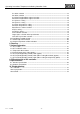
Operating Instructions Temperature Indicating Controller CS4S --- CONTENTS --1. Model name and Order Code ····················································································· 6 2. Name and functions of the sections ········································································ 7 3. Mounting to control panel 3.1 Site selection ···················································································································· 8 3.
Operating Instructions Temperature Indicating Controller CS4S A1 action selection ·········································································································· 18 A2 action selection ·········································································································· 18 A1 action Energized/Deenergized selection ···································································· 18 A2 action Energized/Deenergized selection ·································
Operating Instructions Temperature Indicating Controller CS4S 1. Model Name and Order Code CS4S - 3 A /M Control 3 characteristic Alarm 1 (A1) A Control output R S A Input M Power supply H L Case colour Instrument configuration Options B - - -...
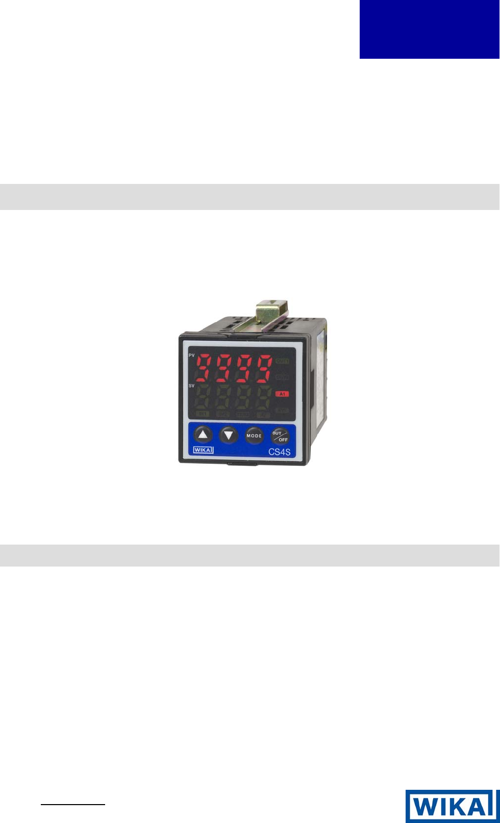
Operating Instructions Temperature Indicating Controller CS4S 2. Name and functions of the sections Indications: (1) (1) PV PV display Indicates the process variable (PV) with a (2) red LED. (2) SV SV display (3) Indicates the setting value (SV) or manipulated variable (MV) with a green LED. (4) (3) SV1 Set value 1 indicator When set value 1 (SV1) is selected, a green LED lights. (4) SV2 Set value 2 indicator (11) (12) (13) (14) When set value 2 (SV2) is selected, a yellow LED lights.
Operating Instructions Temperature Indicating Controller CS4S 3. Mounting to control panel 3.
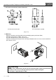
Operating Instructions Temperature Indicating Controller CS4S 3.4 CT (Current transformer) external dimension CTL-6S (for 5A, 10A, 20A) CTL-12-S36-10L1 (for 50A) (Fig. 3.4-1) 3.5 Mounting Mount the controller vertically to fulfill the Dust-proof/Drip-proof specification (IP66). Mountable panel thickness: Within 1 to 15 mm Insert the controller from the front side of the panel. Attach the mounting brackets by the holes at the top and bottom of the case and secure the controller in place with the screws.
Operating Instructions Temperature Indicating Controller CS4S 4. Wiring connection Warning Turn the power supply to the instrument off before wiring or checking it. Working or touching the terminal with the power switched on may result in Electric Shock causing severe injury or death. 3A 250V AC POWER SUPPLY 100 to 240V AC CT OUT1 NO YA A 3A 250V AC OUT A1 2 EVT SV2 NO NO 0.
Operating Instructions Temperature Indicating Controller CS4S Lead wire solderless terminal Use a solderless terminal with isolation sleeve that fits in the M3 screw as shown below. The torque is approximately 0.6 Nm to 1.0 Nm. 3.2mm 5.8mm or less 5.8mm or less 3.2mm (Fig. 4-2) Option: Heater burnout alarm (1) This alarm is not available for detecting heater current under phase control. (2) Use the current transformer (CT) provided and pass one lead wire of the heater circuit into the hole of the CT.
Operating Instructions Temperature Indicating Controller CS4S 5.1 Setup flow chart PV/SV display mode OUT/OFF ] or Control output OFF function [ Auto/Manual control function (*1) (approx. 1s) MODE + MODE + MODE (approx.
Operating Instructions Temperature Indicating Controller CS4S + + MODE (approx.
Operating Instructions Temperature Indicating Controller CS4S 5.2 Main setting mode Character Name, Function, Setting range SV1 • Sets set value 1. • Setting range: SV low limit to SV high limit SV2 • Sets set value 2. • Available only when the option [SV2] is applied. • Setting range: SV low limit to SV high limit Default value 0 °C 0 °C 5.3 Sub setting mode Character V1.
Operating Instructions Temperature Indicating Controller CS4S . , XX.X indicated in turn OUT2 proportional cycle setting • Sets proportional cycle for OUT2. • Not available if the option [DT2] is not applied or when OUT2 is ON/OFF action. • Setting range: 1 … 120 seconds A1 setting • Sets action point for A1 output. • Not available if No alarm action is selected in A1 action selection • Refer to (Table 5.3-1). A2 setting • Sets action point for A2 output.
Operating Instructions Temperature Indicating Controller CS4S 5.4 Auxiliary function setting mode 1 Character V1.1 • 10/2006 Name, Function, Setting range Default value Setting value lock selection Unlock • Locks the setting values to prevent setting errors. The setting item to be locked depends on the designation. • When Lock 1 or Lock 2 is designated, PID Auto-tuning and Auto-reset cannot be carried out. • (Unlock) : All setting values can be changed.
Operating Instructions Temperature Indicating Controller CS4S 5.5 Auxiliary function setting mode 2 Character V1.1 • 10/2006 Name, Function, Setting range Default value Input type selection K (–200 … 1370 °C) • The input type can be selected from thermocouple (10 types), RTD (2 types), DC current (2 types) and DC voltage (4 types), and the unit °C/°F can be selected as well.
Operating Instructions Temperature Indicating Controller CS4S OUT1 low limit setting • Sets the low limit value of OUT1. Not available when OUT1 is ON/OFF action. • Setting range: –5 % to OUT1 high limit value (Setting less than 0 % is only effective to Control output analogue current signal) OUT1 ON/OFF action hysteresis setting • Sets ON/OFF action hysteresis for OUT1. • Available only when OUT1 is ON/OFF action • Setting range: 0.1 … 100.
Operating Instructions Temperature Indicating Controller CS4S A1 hysteresis setting • Sets hysteresis for A1. • Not available if No alarm action is selected in A1 action selection • Setting range: 0.1 … 100.0 °C (°F) or 1 … 1000 A2 hysteresis setting • Sets hysteresis for A2. • Not available if option [2AS] or [2AL] is not added or if No alarm action is selected in A2 action selection • Setting range: 0.1 … 100.0 °C (°F) or 1 … 1000 A1 action delayed timer setting • Sets action delayed timer for A1.
Operating Instructions Temperature Indicating Controller CS4S Energized/Deenergized When [alarm action energized] is selected, the alarm output (between terminals 3-4, or 3-5) is conducted (ON) while the alarm output indicator is lit. The alarm output is not conducted (OFF) while the alarm output indicator is not lit. When [alarm action deenergized] is selected, the alarm output (between terminals 3-4, or 3-5) is not conducted (OFF) while the alarm output indicator is lit.
Operating Instructions Temperature Indicating Controller CS4S 6. Running After the controller has been mounted to the control panel and wiring is completed, it can be started in the following manner. (1) Turn the power supply to the CS4S ON. • For approx. 3s after the power is switched ON, the sensor input character and the temperature unit are indicated on the PV display and input range high limit value is indicated on the SV display. See (Table 5-1).
Operating Instructions Temperature Indicating Controller CS4S 7.
Operating Instructions Temperature Indicating Controller CS4S 7.
Operating Instructions Temperature Indicating Controller CS4S 7.5 OUT2 (Heating/Cooling control) action Heating P-band (Cooling P-band) ON ON Control action (Cooling action) Heating action OFF OFF SV setting Control output relay (OUT1) Control output logic level DC 0/12 V (OUT1) Control output analogue current signal (4 … 20 mA) (OUT1) 6 6 6 7 7 7 Cycle action is performed according to deviation.
Operating Instructions Temperature Indicating Controller CS4S 7.6 OUT2 (Heating/Cooling control) action (When setting Dead band) Heating P-band Dead band (Cooling P-band) ON ON Control action (Cooling action) Heating action OFF OFF SV setting 6 Control output relay (OUT1) 6 6 7 7 7 Cycle action is performed according to deviation.
Operating Instructions Temperature Indicating Controller CS4S 7.7 OUT2 (Heating/Cooling control) action (When setting Overlap band) Heating P-band Cooling P-band Overlap band ON ON (Cooling action) Heating action Control action OFF OFF SV setting Control output relay (OUT1) 6 6 6 7 7 7 Cycle action is performed according to deviation. 3 Non-contact relay output (OUT2) 3 5 5 5 Cycle action is performed according to deviation.
Operating Instructions Temperature Indicating Controller CS4S 8. PID auto-tuning of this controller In order to set each value of P, I, D and ARW automatically, fluctuation is applied to the controlled object to get an optimal value. One of 3 types of fluctuation below is automatically selected. (1) When the difference between the setting value and processing temperature is large as the temperature rises.
Operating Instructions Temperature Indicating Controller CS4S 9. Specifications 9.1 Standard specifications : Flush Mounting method Setting method : Input system using membrane sheet key Display PV display : Red LED 4 digits, character size 10.2 x 4.9 mm (H x W) SV display : Green LED 4 digits, character size 8.8 x 4.9 mm (H x W) Accuracy (Setting and Indication): Thermocouple : Within ±0.
Operating Instructions Temperature Indicating Controller CS4S Control action PID action (with auto-tuning function) PI action : When derivative time is set to 0 PD action (with auto reset function) : When integral time is set to 0 P action (with auto reset function) : When derivative and integral times are set to 0. ON/OFF action : When proportional band is set to 0 or 0.0 OUT1 proportional band : 0 … 1000 °C (2000 °F), 0.0 … 999.9 °C (°F) or 0.0 … 100.0 % (ON/OFF action when set to 0 or 0.
Operating Instructions Temperature Indicating Controller CS4S Attached functions : [Setting value lock], [Sensor correction], [Auto/manual control switching], [Input burnout indication] Thermocouple and RTD inputs If the input value exceeds the Indication range high limit value, the PV display blinks “ ”, and if ”.
Operating Instructions Temperature Indicating Controller CS4S [Burnout] When the thermocouple or RTD input is burnt out, OUT1 and OUT2 are turned off (for Control output ”. analogue current signal: OUT1 low limit value, OUT2 low limit value) and PV display blinks “ [Self-diagnosis] The CPU is monitored by a watchdog timer, and when any abnormal status is found on the CPU, the controller is switched to warm-up status.
Operating Instructions Temperature Indicating Controller CS4S Heating/Cooling control [option code: DT2] The specification of Heating side is the same as that of OUT1. OUT2 proportional band : 0.0 … 10.0 times OUT1 proportional band (ON/OFF action when set to 0.0) OUT2 integral time : The same as that of OUT1. OUT2 derivative time : The same as that of OUT1. OUT2 proportional cycle : 1 … 120 seconds Overlap band/Dead band setting range: Thermocouple, RTD inputs : –100.0 … 100.
Operating Instructions Temperature Indicating Controller CS4S 10. Troubleshooting If any malfunctions occur, refer to the following items, after checking the power supply to the controller. 10.1 Indication Problem PV display is indicating ]. [ [ ] is blinking on the PV display. [ ] is blinking on the PV display. The PV display keeps indicating the value which was set in the Scaling low limit setting. V1.1 • 10/2006 Presumed cause and solution • Control output OFF function is working.
Operating Instructions Temperature Indicating Controller CS4S The indication of PV display is abnormal or unstable. The PV display is ]. indicating [ • Is sensor input or temperature unit (°C or °F) correct? Select the proper sensor input and temperature unit (°C or °F). • Sensor correcting value is unsuitable. Set the value suitably. • Is the specification of the sensor correct? Set the sensor to the proper specification. • AC leaks into the sensor circuit. Use an ungrounded type sensor.