Operating instructions Betriebsanleitung Hand-Held thermometer, models CTH6300 and CTH6500 GB Hand-Held Thermometer, Typen CTH6300 und CTH6500 D Hand-Held thermometer, models CTH6300 and CTH6500
GB Operating instructions, models CTH6300 and CTH6500 Page D Betriebsanleitung, Typen CTH6300 und CTH6500 Seite 3 - 42 41 - 78 Prior to starting any work, read the operating instructions! Keep for later use! Vor Beginn aller Arbeiten Betriebsanleitung lesen! Zum späteren Gebrauch aufbewahren! 2 WIKA operating instructions, models CTH6300 and CTH6500 2079988.02 04/2013 GB/D © 2013 WIKA Alexander Wiegand SE & Co. KG All rights reserved. / Alle Rechte vorbehalten.
Contents Contents 2079988.02 04/2013 GB/D 1. 2. 2.1 2.2 2.3 3. 4. 4.1 4.2 4.3 4.4 4.5 4.6 4.7 5. 6. 6.1 6.2 6.3 6.4 6.4.1 6.4.2 6.4.3 6.4.4 6.4.
1. General information 1. General information ■■ The hand-held thermometers model CTH6300 and CTH6500 described in the operating instructions have been designed and manufactured using state-of-the-art technology. All components are subject to stringent quality and environmental criteria during production. Our management systems are certified to ISO 9001 and ISO 14001. ■■ These operating instructions contain important information on handling the instrument.
1. General information / 2. Safety Explanation of symbols WARNING! ... indicates a potentially dangerous situation that can result in serious injury or death, if not avoided. GB CAUTION! ... indicates a potentially dangerous situation that can result in light injuries or damage to equipment or the environment, if not avoided. Information ... points out useful tips, recommendations and information for efficient and trouble-free operation. DANGER! ... identifies hazards caused by electrical power.
2. Safety The instrument has been designed and built solely for the intended use described here, and may only be used accordingly. The technical specifications contained in these operating instructions must be observed. If the instrument is transported from a cold into a warm environment, the formation of condensation may result in instrument malfunction. Before putting it back into operation, wait for the instrument temperature and the room temperature to equalise.
2. Safety 2.3 Special hazards DANGER! Danger of death caused by electric current Upon contact with live parts, there is a direct danger of death. ■■ Operation or charging using a defective power supply unit (e.g. short circuit from the mains voltage to the output voltage) can result in life-threatening voltages at the instrument! ■■ Only use the mains connector approved by WIKA for the precision hand-held thermometer. ■■ Never use a damaged or worn-looking battery charger. 2079988.
2. Safety / 3. Specifications WARNING! ■■ To avoid false readings, which could lead to possible electric shock or personal injury, replace the battery as soon as the battery indicator appears. GB The safety of the operator may be endangered if, for example: ■■ there is visible damage to the instrument. ■■ the instrument is not working as specified. ■■ the instrument has been stored under unsuitable conditions for an extended period of time.
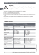
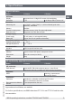
3. Specifications Digital indicator Model CTH6300 Indication Display Large two-line 4 1/2 digit-LCD screen with backlighting Resolution Functions Measuring rate 0.1 K CTH6500 GB 0.01 K up to 200 °C, then 0.
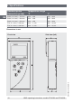
3. Specifications Temperature range °C °F Pt100, d = 3 mm, l = 150 mm -200 ... +450 -392 ... +842 Pt100, d = 6 mm, l = 300 mm -200 ... +450 -392 ... +842 Pt100, d = 3 mm, l = 300 mm TC K, d = 3 mm, l = 300 mm TC K, d = 3 mm, l = 500 mm -200 ... +450 -200 ... +1,100 -200 ... +1,100 -392 ... +842 -392 ... +2,012 -392 ... +2,012 Dimensions in mm Front view 10 Side view (left) WIKA operating instructions, models CTH6300 and CTH6500 2079988.
3. Specifications / 4. Design and function View from below (1-channel instrument) GB 4. Design and function 4.1 Description Universally applicable hand-held thermometers for demanding, mobile temperature measurement, distinguished by flexibility and easy handling. In addition to Pt100 resistance thermometers, they can also process signals from typical thermocouples. Thus temperatures from -200 ... +1,500 °C can be measured.
4. Design and function 4.2 Scope of delivery CTH6300 ■■ 3.1 calibration certificate per DIN EN 10204 ■■ Choice of temperature probes CTH6500 ■■ Hand-held thermometer model CTH6500 incl. 9 V battery ■■ 3.1 calibration certificate per DIN EN 10204 ■■ Choice of temperature probes Cross-check scope of delivery with delivery note. 4.
4. Design and function 5) Function keys Configuration of the instrument 6) ON/OFF button Turning the instrument on and off GB 7) ESC key Back to measuring mode 4.4 Voltage supply The BAT segment indicates that the battery must be replaced soon. At this point correct measurements can be performed for approx. 1 hour. A 9 V battery is used as voltage supply of the instrument. Replacing batteries For battery replacement switch off the instrument and open the battery compartment attached on the rear side.
4. Design and function 4.5 Temperature probe Different connection options of different temperature probes guarantee flexibility. Temperature probes for model CTH6300/CTH6500 Fig. top: immersion probe Fig. bottom: penetration probe Additional temperature probes for model CTH6500 Section through the combined temperature-humidity probe Fig. top: combined temperature-humidity probe Fig. bottom: vane flow probe 14 WIKA operating instructions, models CTH6300 and CTH6500 2079988.
4. Design and function 4.5.1 Connecting/replacing the temperature probe WARNING! Only use the supplied temperature probes! Switch off the instrument for probe replacement. Before switching the instrument on, connect the probe, otherwise it may not be correctly identified by the instrument. GB The digital instrument and the temperature probe are connected to each other electrically by means of a separate connection cable. The 8-pin plug contact at the probe should be used preferably for probe replacement.
4. Design and function 4.6.2 Probe connection thermocouple Measuring channel 1 and 2 GB Pt100 2-wire Soldering side NiCr-Ni thermocouple International colour code for thermocouples Thermocouple DIN 43722 DIN 43710 ANSI MC 96.
4. Design and function 4.6.3 Probe connection vane Mini Air Measuring channel 1 and 2 GB Soldering side yellow white black Mini Air vane 4.6.4 Adapter of thermocouple female connector for connection to DIN connector Measuring channel 1 and 2 Pt100 2-wire 2079988.
4. Design and function 4.7 Operating and display elements GB 6 1 5 4 3 2 1) Probe holder 3) Second connection port for temperature probe 4) USB connection port for PC 5) Keyboard 6) Large LCD display 18 WIKA operating instructions, models CTH6300 and CTH6500 2079988.
5. Transport, packaging and storage 5. Transport, packaging and storage 5.1 Transport Check hand-held thermometer for any damage that may have been caused by transport. Obvious damage must be reported immediately. 5.2 Packaging Do not remove packaging until just before mounting. Keep the packaging as it will provide optimum protection during transport (e.g. change in installation site, sending for repair). 5.3 Storage Permissible conditions at the place of storage: ■■ Storage temperature: -10 ...
6. Commissioning, operation 6. Commissioning, operation 6.1 Commissioning Before switching on connect the probe(s) to the intended female connector of the measuring instrument and make sure that a fully charged 9 V battery is inserted (2 batteries are included in the scope of delivery). The probe connection sockets are marked on the instrument case with 1 or 2 correspondingly. The USB interface is marked next to them. 6.
6. Commissioning, operation For all measuring instruments the measuring channels can be selected according to the model-specific measurement parameters. For the version with only one probe the correct measurement parameter is already set. When using the measuring instruments with several channels and/or different probes make sure that the correct measurement parameter is set. See chapter 6.4.2 "Probe selection Prob". 6.
6. Commissioning, operation 6.4.1 Unit switching °C and °F or % r. h., td or g/m³ [Unit] Press the ENTER/MENU key and select Unit using the arrow keys ▲▼. Then press ENTER/MENU again. A small 1 appears on the left side of the display, it indicates the channel. Use the arrow keys ▲▼ to select the channel for which the displayed unit needs to be changed. Confirm by pressing ENTER/MENU. Depending on the set probe °C/°F or % rH/td/gm³ is displayed on the right side of the display (see chapter 6.4.
6. Commissioning, operation Measurement parameter Probe selection (Prob) Temperature Pt100 (RTD) Temperature Fe-CuNi type J Temperature NiCr-Ni type K Temperature Fe-CuNi type L Temperature NiCrSi-NiSi type N Temperature Pt10Rh-Pt type S Temperature Cu-CuNi type T Humidity % r. h. Flow m/s Pressure Pa Hot wire m/s Temperature LCD display GB Pt13Rh-Pt type R Confirm the required setting by pressing ENTER/MENU. Press ESC to return to the measuring mode again. 2079988.
6. Commissioning, operation 6.4.3 Activating/deactivating display option differential temperature [Lin2] (only for 2-channel instruments) Press the ENTER/MENU key and select Lin 2 using the arrow keys ▲▼. Then press ENTER/MENU again. Now activate or deactivate the display "Differential temperature" T1-T2 using the arrow keys ▲▼. If T1-T2 is visible on the LCD, the differential temperature is active. Confirm the required setting by pressing ENTER/MENU. Press ESC to return to the measuring mode.
6. Commissioning, operation Confirm selection by pressing ENTER/MENU. MENU Unit Prob Lin2 CAL GB Chnl ArEA Lo6 Now use the arrow keys ▲▼ to select the required calibration function. CAL oFF oP1 oP2 Standard linearisation according to DIN IEC 60751 [oFF Use the arrow keys ▲▼ to select CoFF. Press ENTER/MENU to confirm the required setting. Press ESC to return to the measuring mode. 2079988.02 04/2013 GB/D Calibration by code oP1 Use the arrow keys ▲▼ to select oP1.
6. Commissioning, operation Physical calibration oP2 Use the arrow keys ▲▼ to select oP2. Press ENTER/MENU to confirm the required setting. 1 P is displayed in the lower display part. Use the arrow keys ▲▼ to choose from 1-point 1 P-, 2-point 2 P- and 3-point 3 Pcalibration. oP2 1P 2P 3P Example of 1-point calibration: Confirm 1-point calibration 1 P by pressing ENTER/MENU. Go appears on the display. Once the measured value is stable, confirm by pressing ENTER/MENU. After approx.
6. Commissioning, operation Press ENTER/MENU to confirm the required setting. Si_ appears on the display. Use the arrow keys ▲▼ to select the sign: Si_ = the number to be entered is in the negative range (below 0.00 °C) GB Si┘ = the number to be entered is in the positive range Press ENTER/MENU to confirm the required setting. Fd 0 appears on the display. Select the range using the arrow keys ▲▼: Fd 0 = lower than 1,000 °C Fd 1 = higher than 1,000 °C 2079988.
6. Commissioning, operation 6.4.4.1 Calibration function combined probe (humidity/temperature) CAL All humidity probes by WIKA are combined probes. This means that besides the humidity sensor they also contain a temperature sensor. Both measurement parameters are connected to the same measuring channel using the same probe connector. To calibrate both measurement parameters humidity and temperature, the measurement parameter rH must be set first (rel. humidity) (see chapter 6.4.2 "Probe selection Prob").
6. Commissioning, operation MENU Unit Prob Lin2 CAL Chnl ArEA Lo6 Use the arrow keys ▲▼ now to choose between rH for humidity calibration and P °C for temperature calibration. CAL rH P°C Use the arrow keys ▲▼ to select the required calibration function. CAL oFF oP1 oP2 Standard characteristic curve oFF Select oFF by means of the arrow keys ▲▼. Press ENTER/MENU to confirm the required setting. Press ESC to return to the measuring mode. 2079988.
6. Commissioning, operation 6.4.5 Activating/deactivating measuring channels (only for 2-channel instruments) [Chnl] Chnl = Channel = select Press the ENTER/MENU key and select Chnl using the arrow keys ▲▼. Then press ENTER/MENU again. A small 1 appears on the left side of the display, it indicates the channel. Use the arrow keys ▲▼ to select the channel to be activated or deactivated. Confirm selection by pressing ENTER/MENU. Use the arrow keys ▲▼ now to activate on or deactivated off the set channel.
6. Commissioning, operation 6.4.7 Storage management [Lo6] (not possible with CTH6300) Press the ENTER/MENU key and select Lo 6 using the arrow keys ▲▼ (only if a logging device is ordered). Then press ENTER/MENU again. OFF appears in the lower display line. Use the arrow keys ▲▼ to start the logger mode by means of ON now. Confirm selection by pressing ENTER/MENU.
6. Commissioning, operation During storage query the extremes MAX-MIN and the average value AVE are not updated or calculated. GB Clear storage (MAX-MIN-AVE) Press CLEAR once. Clr appears on the display. All extremums (MAX-MIN and AVE) measured up to that moment are deleted. After deletion of the storage the measuring instrument switches back to the measuring mode automatically. 6.6 Changing measurement cycle (FAST mode) Press FAST/▼ once. You are in the Fast mode now.
6. Commissioning, operation / 7. Interface protocol RS-232 6.8 Special functions 6.8.1 Ohm/Microvolt/Volt/Hertz display To display the indicated values in the corresponding basic unit, during switching on simultaneously press FAST/▼ and ON/OFF button and keep them pressed for approx. 3 seconds until the following basic unit is displayed: o = Ohm (Pt100) H = Hertz (flow m/s) u U Microvolt (thermocouples) Volt (humidity) 6.8.2 Zero point adjustment (zero) Keep the Clear key pressed (for approx.
7. Interface protocol RS-232 CTH6500 FC (hex) Read version number of firmware I (ASCII) Enable keyboard Read storage (only for instruments with data logger) 0 (hex) n (ASCII) If data are read out from the instrument using the FC (hex) command, the keyboard is locked. It can be enabled again using the 0 (hex) command. The data are sent by the instrument in the following format. Data type = String The string length depends on whether it is a 1-channel or a 2-channel instrument.
8. Maintenance, cleaning, and recalibration 8. Maintenance, cleaning and recalibration 8.1 Maintenance These hand-held thermometers are maintenance-free. Repairs must only be carried out by the manufacturer. This does not apply to the battery replacement. GB 8.2 Cleaning CAUTION! ■■ Before cleaning, switch off and disconnect the hand-held thermometer from the mains. ■■ Clean the instrument with a moist cloth. ■■ Do not use aggressive cleaning agents.
9. Faults 9. Faults In case of maloperation or faults the instrument helps the operator by means of the following error messages. Indication E15 E19 E1dh E16 36 Cause Measures Wrong probe or no probe connected Connect probe or connect correct probe. "too low" underrange of the measuring range Use the temperature probe according to the technical specifications. See chapter 3 "Specifications".
9. Faults / 10. Dismounting, return and disposal Indication Cause Measures Interruption of the Auto-off function Switch on the Auto-off function again, see chapter 6.7 "AUTOOFF function". Interruption of the Auto-off function Switch on the Auto-off function again, see chapter 6.7 "AUTOOFF function".
10. Dismounting, return and disposal 10.1 Dismounting WARNING! Risk of burns! Let the instrument cool down sufficiently before dismounting it! GB 10.2 Return WARNING! Strictly observe the following when shipping the instrument: All instruments delivered to WIKA must be free from any kind of hazardous substances (acids, bases, solutions, etc.). When returning the instrument, use the original packaging or a suitable transport package. To avoid damage: 1. Wrap the instrument in an antistatic plastic film. 2.
11. Accessories 11.
Appendix: EC Declaration of Conformity for model CTH6500 40 WIKA operating instructions, models CTH6300 and CTH6500 2079988.
Inhalt 2079988.02 04/2013 GB/D Inhalt 1. Allgemeines 2. Sicherheit 2.1 Bestimmungsgemäße Verwendung 2.2 Personalqualifikation 2.3 Besondere Gefahren 3. Technische Daten 4. Aufbau und Funktion 4.1 Beschreibung 4.2 Lieferumfang 4.3 Tastenfeld 4.4 Spannungsversorgung 4.5 Temperaturfühler 4.6 Steckerbelegung 4.7 Bedien- und Anzeigeelemente 5. Transport, Verpackung und Lagerung 6. Inbetriebnahme, Betrieb 6.1 Inbetriebnahme 6.2 Ein-/Ausschalten 6.3 Menüstruktur und Einstellungen 6.4 Menübaum 6.4.
1. Allgemeines 1. Allgemeines ■■ Die in der Betriebsanleitung beschriebenen Hand-Held Thermometer Typ CTH6300 ■■ Diese Betriebsanleitung gibt wichtige Hinweise zum Umgang mit dem Gerät. Voraus- setzung für sicheres Arbeiten ist die Einhaltung aller angegebenen Sicherheitshinweise und Handlungsanweisungen. ■■ Die für den Einsatzbereich des Gerätes geltenden örtlichen Unfallverhütungsvor- schriften und allgemeinen Sicherheitsbestimmungen einhalten.
1. Allgemeines / 2. Sicherheit Symbolerklärung WARNUNG! … weist auf eine möglicherweise gefährliche Situation hin, die zum Tod oder zu schweren Verletzungen führen kann, wenn sie nicht gemieden wird. VORSICHT! … weist auf eine möglicherweise gefährliche Situation hin, die zu geringfügigen oder leichten Verletzungen bzw. Sach- und Umweltschäden führen kann, wenn sie nicht gemieden wird.
2. Sicherheit 2.1 Bestimmungsgemäße Verwendung Die universell einsetzbaren Hand-Held Thermometer für die mobile, anspruchsvolle Temperaturmessung verarbeiten die Signale typischer Thermometer. So können Temperaturen von -200 ... +1.500 °C gemessen werden. Das Gerät ist ausschließlich für den hier beschriebenen bestimmungsgemäßen Verwendungszweck konzipiert und konstruiert und darf nur dementsprechend verwendet werden. Die technischen Spezifikationen in dieser Betriebsanleitung sind einzuhalten.
2. Sicherheit 2.3 Besondere Gefahren GEFAHR! Lebensgefahr durch elektrischen Strom Bei Berührung mit spannungsführenden Teilen besteht unmittelbare Lebensgefahr. ■■ Bei Betrieb oder Laden mit einem defekten Netzgerät (z. B. Kurzschluss von Netzspannung zur Ausgangsspannung) können am Gerät lebensgefährliche Spannungen auftreten! ■■ Nur das von WIKA für das Präzisions-Hand-Held Thermometer zugelassene Netzgerät verwenden. ■■ Kein schadhaftes oder abgenutztes Ladegerät verwenden. D 2079988.
2. Sicherheit / 3. Technische Daten 3. Technische Daten Hand-Held Thermometer (gesamte Messkette) Gerätetyp CTH6300 Fühlertypen Pt100, Thermoelemente Messeingänge 1 oder 2 Messbereich Pt100 Thermoelemente Feuchte Strömung Messunsicherheiten 1) Widerstandsthermometer Typ Pt100 -200 ... +600 °C -392 ... +1.112 °F -200 ... +1.500 °C -392 ... +2.732 °F -200 ... +600 °C -392 ... +1.112 °F -200 ... +1.500 °C -392 ... +2.732 °F -- 0 ... 40 m/s -- 0,1 K von -100 ... +200 °C sonst 0,1 % v.
3. Technische Daten Digitales Anzeigegerät Gerätetyp Anzeige Display Auflösung Funktionen Messrate CTH6300 CTH6500 4 1/2-stellig, großes zweizeilige LCD-Display mit Hintergrundbeleuchtung 0,1 K 0,01 K bis 200 °C, dann 0,1 K 4/s ("slow"); 1.000/s ("fast"); > 1.
3. Technische Daten Standardfühler (Eintauchfühler) °F Pt100, d = 3 mm, l = 150 mm -200 ... +450 -392 ... +842 Pt100, d = 6 mm, l = 300 mm -200 ... +450 -392 ... +842 Pt100, d = 3 mm, l = 300 mm TC K, d = 3 mm, l = 300 mm TC K, d = 3 mm, l = 500 mm -200 ... +450 -200 ... +1.100 -200 ... +1.100 -392 ... +842 -392 ... +2.012 -392 ... +2.012 Abmessungen in mm Frontansicht 48 Ansicht von links WIKA Betriebsanleitung, Typen CTH6300 und CTH6500 2079988.
3. Technische Daten / 4. Aufbau und Funktion Ansicht von unten (1-Kanalgerät) D 4. Aufbau und Funktion 4.1 Beschreibung Die universell einsetzbaren Hand-Held Thermometer für die mobile, anspruchsvolle Temperaturmessung bestechen durch Flexibilität und leichte Handhabung. Neben Pt100-Widerstandsthermometern verarbeiten sie die Signale typischer Thermoelemente. So können Temperaturen von -200 ... +1.500 °C gemessen werden.
4. Aufbau und Funktion 4.2 Lieferumfang CTH6300 ■■ Hand-Held Thermometer Typ CTH6300 inkl. 9-V-Blockbatterie ■■ Kalibrierzertifikat 3.1 nach DIN EN 10204 CTH6500 ■■ Hand-Held Thermometer Typ CTH6500 inkl. 9-V-Blockbatterie ■■ Kalibrierzertifikat 3.1 nach DIN EN 10204 ■■ Temperaturfühler nach Wahl Lieferumfang mit dem Lieferschein abgleichen. 4.
4. Aufbau und Funktion 5) Funktionstasten Konfigurieren des Gerätes 6) EIN/AUS-Taste Ein- und Ausschalten des Gerätes 7) ESC-Taste Zurück zum Messmodus D 4.4 Spannungsversorgung Das Segment BAT zeigt an, dass die Batterie in Kürze ausgewechselt werden müssen. Es können jetzt noch ca. 1 Std. korrekte Messungen durchführen werden. Als Spannungsversorgung des Gerätes dient eine 9-V-Blockbatterie.
4. Aufbau und Funktion 4.5 Temperaturfühler Verschiedene Anschlussmöglichkeiten verschiedener Temperaturfühler gewährleisten Flexibilität. Abb. oben: Eintauchfühler Abb. unten: Einstechfühler Zusätzliche Temperaturfühler für Typ CTH6500 Ausschnitt des TemperaturFeuchte-Kombifühlers Abb. oben: Temperatur-Feuchte-Kombifühler Abb. unten: Flügelrad-Strömungsfühler 52 WIKA Betriebsanleitung, Typen CTH6300 und CTH6500 2079988.
4. Aufbau und Funktion 4.5.1 Temperaturfühler anstecken/wechseln WARNUNG! Nur die mitgelieferten Temperaturfühler verwenden! Zum Fühlerwechsel Gerät ausschalten. Fühler vor dem Einschalten des Gerätes anstecken, sonst wird er vom Gerät evtl. nicht richtig erkannt. Digitalgerät und Temperaturfühler werden mittels eines separaten Verbindungskabels elektrisch miteinander verbunden. Für den Fühlerwechsel sollte bevorzugt der 8-polige Steckkontakt am Fühler benutzt werden.
4. Aufbau und Funktion 4.6.2 Fühleranschluss Thermoelement Messkanal 1 und 2 Pt100 2-Leiter D Lötseite NiCr-Ni-Thermoelement Internationale Kennfarben für Thermoelemente Thermopaar DIN 43722 DIN 43710 ANSI MC 96.
4. Aufbau und Funktion 4.6.3 Fühleranschluss Flügelrad Mini Air Messkanal 1 und 2 D Lötseite gelb weiß schwarz Mini Air Flügelrad 4.6.4 Adapter DIN Stecker auf Thermoelementbuchse Messkanal 1 und 2 Pt100 2-Leiter 2079988.
4. Aufbau und Funktion 4.7 Bedien- und Anzeigeelemente D 6 1 5 4 3 2 1) Fühlerhalterung 3) Zweiter Anschlussport für Temperaturfühler 4) USB-Anschlussport für PC 5) Tastatur 6) Großes LCD-Display 56 WIKA Betriebsanleitung, Typen CTH6300 und CTH6500 2079988.
5. Transport, Verpackung und Lagerung 5. Transport, Verpackung und Lagerung 5.1 Transport Hand-Held Thermometer auf eventuell vorhandene Transportschäden untersuchen. Offensichtliche Schäden unverzüglich mitteilen. 5.2 Verpackung Verpackung erst unmittelbar vor der Montage entfernen. Die Verpackung aufbewahren, denn diese bietet bei einem Transport einen optimalen Schutz (z. B. wechselnder Einbauort, Reparatursendung). 5.3 Lagerung Zulässige Bedingungen am Lagerort: ■■ Lagertemperatur: -10 ...
6. Inbetriebnahme, Betrieb 6. Inbetriebnahme, Betrieb 6.2 Ein-/Ausschalten Durch Betätigen der ON/OFF-Taste wird das Messgerät ein- und ausgeschaltet. Nach dem Einschalten werden auf dem Display für ca. 1,5 Sekunden alle Segmente angezeigt (Vollsegmentanzeige). Anschließend zeigt das Gerät für ca. weitere 1,5 Sekunden den eingestellten Fühler-Kalibriercode sowie die eingestellte Messgröße für Kanal 1 an (z. B. CoFF für DIN-Kennlinie und P für Pt100). Danach werden die Kalibrierdaten für den 2.
6. Inbetriebnahme, Betrieb Bei allen Messgeräten lassen sich die Messkanäle entsprechend der modellspezifischen Messgrößen auswählen. Bei Auslieferung mit nur einem Fühler ist die richtige Messgröße bereits voreingestellt. Darauf achten, dass bei Messgeräten mit mehreren Kanälen und/oder verschiedenen Fühler die richtige Messgröße eingestellt ist. Siehe Kapitel 6.4.2 "Fühlerauswahl Prob". 6.
6. Inbetriebnahme, Betrieb 6.4.1 Einheitenumschaltung °C und °F bzw. % rH, td oder g/m³ [Unit] Unit = Einheit Messeinheit Temperatur (°C = Celsius, °F = Fahrenheit) Messeinheit Feuchte (% rH = relative Feuchte, td = Taupunkt, g/m³ = absolute Feuchte) Drücken Sie die Taste ENTER/MENU und wählen Sie Unit mit Hilfe der Pfeiltasten ▲▼ aus. Danach ENTER/MENU erneut drücken. Auf der linken Displayseite erscheint eine kleine 1, die den Kanal anzeigt.
6. Inbetriebnahme, Betrieb Messgröße Fühlerauswahl (Prob) Temperatur Pt100 (RTD) Temperatur Fe-CuNi Type J Temperatur NiCr-Ni Type K Temperatur Fe-CuNi Type L Temperatur NiCrSi-NiSi Type N Temperatur Pt10Rh-Pt Type S Temperatur Cu-CuNi Type T Feuchte % rH Strömung m/s Druck Pa Hitzdraht m/s Temperatur LCD-Anzeige D Pt13Rh-Pt Type R Mit ENTER/MENU die gewünschte Einstellung bestätigen. Mit ESC gelangen Sie danach wieder in den Messmodus. 2079988.
6. Inbetriebnahme, Betrieb 6.4.3 Anzeigeoption Differenztemperatur aktivieren/deaktivieren [Lin2] (Nur für 2-Kanalgeräte) MENÜ Unit Prob Lin2 CAL Chnl ArEA Lo6 Zur Anzeige der Differenztemperatur müssen beide Kanäle aktiviert sein. 6.4.
6. Inbetriebnahme, Betrieb kleine 1, die den Kanal anzeigt. Mit den Pfeiltasten ▲▼ den Kanal auswählen (1 oder 2) der kalibriert werden soll. Mit ENTER/MENU die Auswahl bestätigen. MENÜ Unit Prob Lin2 CAL Chnl ArEA D Lo6 Mit den Pfeiltasten ▲▼ jetzt die gewünschte Kalibrierfunktion auswählen. CAL oFF oP1 oP2 Standard-Linearisierung gemäß DIN IEC 60751 [oFF Mit Hilfe der Pfeiltasten ▲▼ CoFF auswählen. Mit ENTER/MENU die gewünschte Einstellung bestätigen.
6. Inbetriebnahme, Betrieb Beispiel der Messwertanzeige nach Eingabe einer Fühlerkalibriernummer: Die kleine 1 in der linken Ecke in Verbindung mit dem Anzeigesegment CAL in der Displaymitte zeigt an, dass die Nummernkalibrierung oP1 aktiviert wurde. D Physikalische Kalibrierung oP2 Mit Hilfe der Pfeiltasten ▲▼ oP2 auswählen. Mit ENTER/MENU die gewünschte Einstellung bestätigen. Im unteren Displayteil erscheint 1 P.
6. Inbetriebnahme, Betrieb Mit ENTER/MENU die gewünschte Einstellung bestätigen. Auf dem Display erscheint Si_. Mit den Pfeiltasten ▲▼ das Vorzeichen auswählen: Si_ = einzugebende Zahl ist im negativen Bereich (unter 0,00 °C) Si┘ = einzugebende Zahl ist im positiven Bereich D Mit ENTER/MENU die gewünschte Einstellung bestätigen. Auf dem Display erscheint Fd 0. Mit den Pfeiltasten ▲▼ den Bereich auswählen: Fd 0 = unter 1.000 °C Fd 1 = über 1.000 °C 2079988.
6. Inbetriebnahme, Betrieb Beispiel der Messwertanzeige nach einer physikalischen Kalibrierung gegen ein Vergleichsnormal: Die kleine 2 in der linken Ecke in Verbindung mit dem Anzeigesegment CAL in der Displaymitte zeigt an, dass die physikalische Fühlerkalibrierung oP2 aktiviert wurde. D 6.4.4.1 Kalibrierfunktion Kombifühler (Feuchte/Temperatur) CAL Alle Feuchtefühler der Firma WIKA sind Kombinationsfühler. D. h. neben dem Feuchtesensor beinhalten diese Fühler auch ein Temperatursensor.
6. Inbetriebnahme, Betrieb MENÜ Unit Prob Lin2 CAL Chnl ArEA Lo6 Mit den Pfeiltasten ▲▼ jetzt zwischen rH für Feuchtekalibrierung und P °C für Temperaturkalibrierung auswählen. CAL rH P°C Mit den Pfeiltasten ▲▼ die gewünschte Kalibrierfunktion auswählen. CAL oFF oP1 oP2 Standardkennlinie oFF Wählen Sie mit Hilfe der Pfeiltasten ▲▼ oFF aus. Mit ENTER/MENU die gewünschte Einstellung bestätigen. Mit ESC gelangen Sie danach wieder in den Messmodus. 2079988.
6. Inbetriebnahme, Betrieb 6.4.5 Messkanäle aktivieren/deaktivieren (nur für 2-Kanalgeräte) [Chnl] Alternative: HOLD/MAX/MIN/AVE-Taste 2 Sekunden drücken; damit wird Kanal 2 deaktiviert bzw. aktiviert. MENÜ Unit Prob Lin2 CAL Chnl ArEA Lo6 Es bleibt immer mindestens ein Kanal aktiv! 6.4.6 Flächeneingabe für Volumenstrom [ArEA] Die Eingabe der Flächenmaße ist nur an Geräten für Strömungsmessung möglich.
6. Inbetriebnahme, Betrieb 6.4.7 Speicherverwaltung [Lo6] (nicht möglich bei CTH6300) Drücken Sie die Taste ENTER/MENU und wählen Sie Lo6 mit Hilfe der Pfeiltasten ▲▼ aus (nur wenn die Datenlogger-Ausführung bestellt wurde). Danach ENTER/MENU erneut drücken. In der unteren Displayzeile erscheint OFF. Mit den Pfeiltasten ▲▼ jetzt den Loggermodus mit ON starten. Mit ENTER/MENU die Auswahl bestätigen.
6. Inbetriebnahme, Betrieb sollten Sie den 2. Kanal deaktivieren (siehe Kapitel 6.4.5 "Messkanäle aktivieren/deaktivieren (nur für 2-Kanalgeräte) [Chnl]". Speicher löschen (MAX-MIN-AVE) CLEAR-Taste einmal betätigen. Auf dem Display erscheint Clr. Es werden jetzt alle bis zu diesem Zeitpunkt gemessenen Extrema (MAX-MIN und AVE) gelöscht. Nach dem Löschen des Speichers schaltet das Messgerät automatisch in den Messmodus zurück. 6.6 Messzyklus ändern (FAST-Modus) Drücken Sie die Taste FAST/▼ einmal.
6. Inbetriebnahme, Betrieb / 7. Schnittstellenprotokoll RS-232 6.8 Sonderfunktionen 6.8.1 Ohm/Microvolt/Volt/Hertz-Anzeige Um die angezeigten Werte in der entsprechenden Basiseinheit anzuzeigen, muss beim Einschalten die Taste FAST/▼ und die ON/OFF-Taste für ca. 3 Sekunde gleichzeitig gehalten werden bis die folgende Basiseinheit angezeigt wird: o = Ohm (Pt100) H = Hertz (Strömung m/s) u U Microvolt (Thermoelemente) Volt (Feuchte) 6.8.2 Nullpunktabgleich (Zero) Durch langes Drücken (ca.
7. Schnittstellenprotokoll RS-232 CTH6500 MESSWERT 1 + 2 automatisch erkennen FC (hex) Lese Versionsnummer der Firmware I (ASCII) Tastaturfreigabe n (ASCII) Wenn mit den Befehl FC (hex) Daten aus dem Gerät ausgelesen werden, so wird die Tastatur gesperrt. Diese kann dann mit dem Befehl 0 (hex) wieder freigegeben werden. Die Daten werden im nachfolgendem Format vom Gerät gesendet. Datentyp = String Die Stringlänge ist abhängig ob es ein 1 Kanal oder ein 2 Kanalgerät ist.
8. Wartung, Reinigung und Rekalibrierung 8. Wartung, Reinigung und Rekalibrierung 8.1 Wartung Diese Hand-Held Thermometer sind wartungsfrei. Reparaturen sind ausschließlich vom Hersteller durchzuführen. Ausgenommen ist der Austausch der Batterie. D 8.2 Reinigung VORSICHT! ■■ Vor der Reinigung das Hand-Held Thermometer ordnungsgemäß ausschalten und vom Netz trennen. ■■ Das Gerät mit einem feuchten Tuch reinigen. ■■ Keine aggressiven Reinigungsmittel verwenden.
9. Störungen 9. Störungen Bei Fehlbedienungen oder Gerätestörungen unterstützt das Gerät den Bediener durch folgende Fehlermeldungen. D Anzeige Ursache Maßnahmen Falscher Fühler oder kein Fühler Richtigen Fühler oder Fühler angeschlossen anschließen. „too low” Messbereichsunterschreitung Temperaturfühler innerhalb der technischen Spezifikationen einsetzen. Siehe Kapitel 3 „Technischen Daten“. „too high” Messbereichsüberschreitung Temperaturfühler innerhalb der technischen Spezifikationen einsetzen.
8. Störungen / 9. Demontage, Rücksendung und Entsorgung Anzeige Ursache Maßnahmen Unterbrechung der Auto-offFunktion Auto-Off Funktion wieder einschalten, siehe Kapitel 6.7 „AUTO-OFF-Funktion“. Unterbrechung der Auto-offFunktion Auto-Off Funktion wieder einschalten, siehe Kapitel 6.7 „AUTO-OFF-Funktion“.
9. Demontage, Rücksendung und Entsorgung 10.1 Demontage WARNUNG! Verbrennungsgefahr! Vor dem Ausbau das Gerät ausreichend abkühlen lassen! D 10.2 Rücksendung WARNUNG! Beim Versand des Gerätes unbedingt beachten: Alle an WIKA gelieferten Geräte müssen frei von Gefahrstoffen (Säuren, Laugen, Lösungen, etc.) sein. Zur Rücksendung des Gerätes die Originalverpackung oder eine geeignete Transportverpackung verwenden. Um Schäden zu vermeiden: 1. Das Gerät in eine antistatische Plastikfolie einhüllen. 2.
11. Zubehör 11.
Anlage: Konformitätserklärung Typ CTH6500 78 WIKA Betriebsanleitung, Typen CTH6300 und CTH6500 2079988.
WIKA global Europe Austria WIKA Messgerätevertrieb Ursula Wiegand GmbH & Co. KG 1230 Vienna Tel. (+43) 1 86916-31 Fax: (+43) 1 86916-34 E-mail: info@wika.at www.wika.at Belarus WIKA Belarus Ul. Zaharova 50B Office 3H 220088 Minsk Tel. (+375) 17-294 57 11 Fax: (+375) 17-294 57 11 E-mail: info@wika.by www.wika.by Benelux WIKA Benelux 6101 WX Echt Tel. (+31) 475 535-500 Fax: (+31) 475 535-446 E-mail: info@wika.nl www.wika.nl Bulgaria WIKA Bulgaria EOOD Bul. „Al. Stamboliiski“ 205 1309 Sofia Tel.
WIKA global Asia China WIKA International Trading (Shanghai) Co., Ltd. A2615, NO.100, Zunyi Road Changning District Shanghai 200051 Tel. (+86) 21 538525-72 Fax: (+86) 21 538525-75 E-mail: info@wika.cn www. wika.com.cn WIKA Instrumentation (Suzhou) Co., Ltd. 81, Ta Yuan Road, SND, Suzhou 215011 Tel. (+86) 512 68788000 Fax: (+86) 512 68780300 E-mail: info@wika.cn www. wika.com.cn India WIKA Instruments India Pvt. Ltd. Village Kesnand, Wagholi Pune - 412 207 Tel.