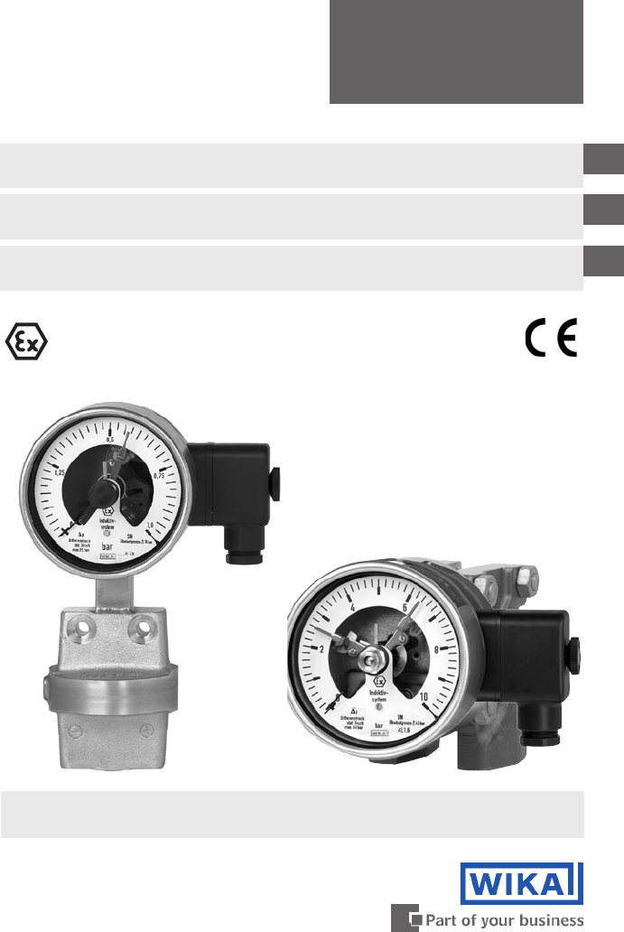
Operating Instructions Betriebsanleitung Mode d'emploi Pressure gauges Model 7 per directive 94/9/EC (ATEX) with inductive contacts Model 831 GB Druckmessgeräte Typ 7 nach Richtlinie 94/9/EG (ATEX) mit Induktivkontakten Typ 831 D Manomètres Type 7 selon directive 94/9/EG (ATEX) avec contacts inductifs Type 831 F II 2 GD c TÜV 03 ATEX 2304 X Model 732.51.100 per ATEX with inductive contact Model 831.1 Model 732.14.100 per ATEX with inductive contact Model 831.
GB Operating instructions Model 7 per ATEX with Model 831 D Betriebsanleitung Typ 7 nach ATEX mit Typ 831 F Mode d’emploi Type 7 selon ATEX 3-23 Seite 25-45 Page 47-53 2080250 07/2009 GB/D/F avec Type 831 Page
Contents Contents 1. Safety instructions 4 2. Description 4 3. Technical data and intended use 5 4. Switch contacts 7 5. Commissioning 9 6. Maintenance and servicing / cleaning 9 7. Repairs 9 8. Disposal 9 Appendix 1: Declaration of conformity for Models 73X.51 and 73X.31 10 Appendix 2: Declaration of conformity for Models 73X.14 and 76X.
1. Safety instructions / 2. Description 1. Safety instructions ! GB Caution The appropriate national safety regulations (i.e. VDE 0100 / EN 60 079-14 / EN 837-2) must be observed when installing, commissioning and operating these instruments. Only work on the gauge with the voltage disconnected Serious injuries and/or damage can occur should the appropriate regulations not be observed Only appropriately qualified personnel should work on these instruments 2.
3. Technical data and intended use 3. Technical data and intended use Pressure limitation Model 73X.51/31: GB Steady: full scale value Fluctuating: 0.9 x full scale value Table 1: Max. working pressure / Overpressure safety maximum in bar Pressure ranges Working pressure max. Overpressure safety, single, (static pressure) dual or alternating sides Standard Option Standard Option 0 ... 16 to 0 ... 40 mbar 0 ... 60 to 0 ... 250 mbar 0 ... 400 mbar 0 ... 0.6 bar 0 ... 1 bar 0 ... 1.6 bar 0 ... 2.5 to 0 ..
3. Technical data and intended use Operating Temperature -20 ... +60 °C Medium: The permissible medium temperature does not only depend on the instrument design, but also on the ignition temperature of the surrounding explosive atmosphere. Both aspects must be taken into account. For maximum permissible medium temperatures see Table 2. Attention! In the case of gaseous substances, the temperature may increase due to compression warming.
3. Technical data and intended use / 4. Switch contacts Permissible vibration load at the mounting point The instruments should always be installed in locations free from vibration. If necessary, it is possible to isolate the instrument from the mounting point by installing a flexible connection line between the measuring point and the pressure gauge and mounting the instrument on a suitable bracket.
4. Switch contacts Suitable switch amplifiers are e.g.: Circuit Sensor type (s. Ex-certific.) Model designation Fa. Pepperl & Fuchs EC-type examination certificate WIKAModel Model 1 KFD2-SR2-Ex1 KFD2-SR2 Ex2 KFA6-SR2-Ex1 KFA6-SR2-Ex2 KFD2-SH-Ex1 KHA6-SH-Ex1 PTB 00 ATEX 2080 PTB 00 ATEX 2080 PTB 00 ATEX 2081 PTB 00 ATEX 2081 PTB 00 ATEX 2042 PTB 00 ATEX 2043 904.31 904.32 904.28 904.29 904.33 904.
5. Commissioning ... 8. Disposal 5. Commissioning During the commissioning process pressure peaks must be avoided at all costs. Open the shut-off valves slowly. GB 6. Maintenance and servicing / cleaning The instruments require no maintenance or servicing. The indicator and switching function should be checked once or twice every 12 months. The instrument must be disconnected from the process to check with a pressure testing device.
Appendix 1 2080250 07/2009 GB/D/F GB 10 WIKA Operating instructions pressure gauges Model 7 with 831 per ATEX
Appendix 2 2080250 07/2009 GB/D/F GB WIKA Operating instructions pressure gauges Model 7 with 831 per ATEX 11
Appendix 3 2080250 07/2009 GB/D/F GB 12 WIKA Operating instructions pressure gauges Model 7 with 831 per ATEX
Appendix 3 2080250 07/2009 GB/D/F GB WIKA Operating instructions pressure gauges Model 7 with 831 per ATEX 13
Appendix 3 2080250 07/2009 GB/D/F GB 14 WIKA Operating instructions pressure gauges Model 7 with 831 per ATEX
Appendix 4 2080250 07/2009 GB/D/F GB WIKA Operating instructions pressure gauges Model 7 with 831 per ATEX 15
Appendix 4 2080250 07/2009 GB/D/F GB 16 WIKA Operating instructions pressure gauges Model 7 with 831 per ATEX
Appendix 4 2080250 07/2009 GB/D/F GB WIKA Operating instructions pressure gauges Model 7 with 831 per ATEX 17
Appendix 4 2080250 07/2009 GB/D/F GB 18 WIKA Operating instructions pressure gauges Model 7 with 831 per ATEX
Appendix 5 2080250 07/2009 GB/D/F GB WIKA Operating instructions pressure gauges Model 7 with 831 per ATEX 19
Appendix 5 2080250 07/2009 GB/D/F GB 20 WIKA Operating instructions pressure gauges Model 7 with 831 per ATEX
Appendix 5 2080250 07/2009 GB/D/F GB WIKA Operating instructions pressure gauges Model 7 with 831 per ATEX 21
Appendix 5 2080250 07/2009 GB/D/F GB 22 WIKA Operating instructions pressure gauges Model 7 with 831 per ATEX
Appendix 5 2080250 07/2009 GB/D/F D WIKA Betriebsanleitung Druckmessgeräte Typ 7 mit 831 nach ATEX 23
2080250 07/2009 GB/D/F D 24 WIKA Betriebsanleitung Druckmessgeräte Typ 7 mit 831 nach ATEX
Inhalt Inhalt 1. Sicherheitshinweise 26 2. Beschreibung 26 3. Technische Daten und bestimmungsgemäße Verwendung 27 4. Elektrische Schaltkontakte 29 5. Inbetriebnahme 31 6. Wartung / Reinigung 31 7. Reparaturen 31 8. Entsorgung 31 Anlage 1: Konformitätserklärung für Typen 73X.51 und 73X.31 32 Anlage 2: Konformitätserklärung für Typen 73X.14 und 76X.
1. Sicherheitshinweise / 2. Beschreibung 1. Sicherheitshinweise ! Vorsicht Alle Arbeiten dürfen nur im spannungslosen Zustand erfolgen Bei Nichtbeachten der entsprechenden Vorschriften können schwere Körperverletzungen und / oder Sachschäden auftreten Nur entsprechend qualifiziertes Personal darf an diesen Geräten arbeiten 2.
3. Technische Daten und bestimmungsgemäße Verwendung 3. Technische Daten und bestimmungsgemäße Verwendung Druckbelastbarkeit Typ 73X.51/31: Ruhebelastung: Skalenendwert Wechselbelastung: 0,9 x Skalenendwert D Tabelle 1: Max. Betriebsdruck / Überlastbarkeit in bar Anzeigebereiche max. Betriebsdruck (statischer Druck) Standard Option Überlastbarkeit ein-, beid- u. wechselseitig Standard Option 0 ... 16 bis 0 ... 40 mbar 0 ... 60 bis 0 ... 250 mbar 0 ... 400 mbar 0 ... 0,6 bar 0 ... 1 bar 0 ... 1,6 bar 0 .
3. Technische Daten und bestimmungsgemäße Verwendung Zulässige Temperaturen Umgebung: -20 ... +60 °C Messstoff: D Die zulässige Messstofftemperatur hängt außer von der Gerätebauart auch von der Zündtemperatur der umgebenden Gase, Dämpfe bzw. Stäube ab. Beide Aspekte sind zu berücksichtigen. Maximal zulässige Grenzwerte siehe Tabelle 2. Achtung! Bei gasförmigen Stoffen kann sich die Temperatur durch Kompressionswärme erhöhen. In solchen Fällen muss ggf. die Druckänderungsgeschwindigkeit gedrosselt bzw.
3. Technische Daten ... / 4. Elektrische Schaltkontakte Zulässige Schwingungsbelastung am Einbauort Die Geräte sollten grundsätzlich nur an Stellen ohne Schwingungsbelastung eingebaut werden Gegebenenfalls kann z. B. durch eine flexible Verbindungsleitung von der Messstelle zum Druckmessgerät und die Befestigung über eine Messgerätehalterung eine Entkopplung vom Einbauort erreicht werden.
4. Elektrische Schaltkontakte Die zulässigen Grenzwerte für Ui, Ii und Pi der eigensicheren Versorgungsstromkreise hängen vom Initiatortyp ab. Sie sind aus den jeweiligen EG-Baumusterprüfbescheinigungen zu entnehmen. (Der Initiatortyp ist auf dem Anschlussschild des Druckmessgerätes angegeben.) Geeignete Trennschaltverstärker sind z. B.: Stromkreis Sensortyp (s. Ex-Schein) Typ 1 Typ 2 Standard Standard Standard Standard SN-Sensoren SN-Sensoren Typenbezeichnung Fa.
5. Inbetriebnahme ... 8. Entsorgung 5. Inbetriebnahme Bei Inbetriebnahme Druckstöße unbedingt vermeiden, Absperrventile langsam öffnen. D 6. Wartung / Reinigung Die Geräte sind wartungsfrei. Eine Überprüfung der Anzeige und der Schaltfunktion sollte etwa 1 bis 2 mal pro Jahr erfolgen. Dazu ist das Gerät vom Prozess zu trennen und mit einer Druckprüfvorrichtung zu kontrollieren. Reinigen der Geräte mit einem (in Seifenlauge) angefeuchteten Tuch. Zur Reinigung sind die Geräte vom Netz zu trennen.
Anlage 1 2080250 07/2009 GB/D/F D 32 WIKA Betriebsanleitung Druckmessgeräte Typ 7 mit 831 nach ATEX
Anlage 2 2080250 07/2009 GB/D/F D WIKA Betriebsanleitung Druckmessgeräte Typ 7 mit 831 nach ATEX 33
Anlage 3 2080250 07/2009 GB/D/F D 34 WIKA Betriebsanleitung Druckmessgeräte Typ 7 mit 831 nach ATEX
Anlage 3 2080250 07/2009 GB/D/F D WIKA Betriebsanleitung Druckmessgeräte Typ 7 mit 831 nach ATEX 35
Anlage 3 2080250 07/2009 GB/D/F D 36 WIKA Betriebsanleitung Druckmessgeräte Typ 7 mit 831 nach ATEX
Anlage 4 2080250 07/2009 GB/D/F D WIKA Betriebsanleitung Druckmessgeräte Typ 7 mit 831 nach ATEX 37
Anlage 4 2080250 07/2009 GB/D/F D 38 WIKA Betriebsanleitung Druckmessgeräte Typ 7 mit 831 nach ATEX
Anlage 4 2080250 07/2009 GB/D/F D WIKA Betriebsanleitung Druckmessgeräte Typ 7 mit 831 nach ATEX 39
Anlage 4 2080250 07/2009 GB/D/F D 40 WIKA Betriebsanleitung Druckmessgeräte Typ 7 mit 831 nach ATEX
Anlage 5 2080250 07/2009 GB/D/F D WIKA Betriebsanleitung Druckmessgeräte Typ 7 mit 831 nach ATEX 41
Anlage 5 2080250 07/2009 GB/D/F D 42 WIKA Betriebsanleitung Druckmessgeräte Typ 7 mit 831 nach ATEX
Anlage 5 2080250 07/2009 GB/D/F D WIKA Betriebsanleitung Druckmessgeräte Typ 7 mit 831 nach ATEX 43
Anlage 5 2080250 07/2009 GB/D/F D 44 WIKA Betriebsanleitung Druckmessgeräte Typ 7 mit 831 nach ATEX
Anlage 5 2080250 07/2009 GB/D/F D WIKA Betriebsanleitung Druckmessgeräte Typ 7 mit 831 nach ATEX 45
2080250 07/2009 GB/D/F D 46 WIKA Betriebsanleitung Druckmessgeräte Typ 7 mit 831 nach ATEX
Sommaire Sommaire 1. Consignes de sécurité 48 2. Description 48 3. Caractéristiques techniques et utilisation correspondante 49 4. Commutateurs 51 5. Mise en service 53 6. Entretien / Nettoyage 53 7. Réparations 53 8.
1. Consignes de sécurité / 2. Description 1. Consignes de sécurité ! Avertissement Les prescriptions de sécurité nationales en vigueur (par exemple VDE 0100 / EN 60 079-14 / EN 837-2) doivent absolument être respectées lors du montage, de la mise en service et de l‘utilisation des instruments ici présentés.
3. Caractéristiques techniques et utilisation correspondante 3. Caractéristiques techniques et utilisation correspondante Limitations en pression Type 73X.51/31: Charge statique: fin d'échelle Charge dynamique: 90 % de fin d'échelle Tableau 1: Pression de service maxi / surpression admissible en bar Etendues de mesure Pression maxi (pression statique) Standard Option Surcharge bi-latérale Standard Option 0 ... 16 à 0 ... 40 mbar 0 ... 60 à 0 ... 250 mbar 0 ... 400 mbar 0 ... 0,6 bar 0 ... 1 bar 0 ...
3. Caractéristiques techniques et utilisation correspondante Températures autorisées Ambiante: -20 ... +60 °C Fluide: La température de fluide autorisée dépend, en plus de la conception de l'appareil, également de la température d'inflammation du gaz, des vapeurs ou des poussières de l'environnement. Ces deux paramètres sont à prendre en considération. Voir le tableau 2 pour les limites de température autorisées.
3. Caractéristiques techniques ... / 4. Commutateurs Contrainte de vibration admissible sur le point de montage Les appareils ne devraient en principe être installés que sur des applications exemptes de vibrations Le cas échéant, on peut obtenir un isolement du point de mesure en utilisant une liaison flexible entre le manomètre et le point de mesure et en le fixant à l’aide d’un support d’appareil mural.
4. Commutateurs Les valeurs limites autorisées pour Ui, Ii et Pi de l‘alimentation intrinsèque des circuits dépendent du type de détecteur. Ces valeurs sont indiquées dans les procédures d‘attestation de la conformité CE. (Le type de détecteur est indiqué sur le schéma de branchement du manomètre). Exemple pour relais d‘amplification appropriés: Circuit Type 1 Type 2 Type de détecteur Code de désignation Attestation Etbs.
5. Mise en service ... 8. Mise au rebus 5. Mise en service Lors de la mise en service il faut absolument éviter les coups de bélier. Ouvrir lentement les vannes de fermeture. 6. Entretien / Nettoyage Les instruments ne requièrent aucun entretien. Un contrôle de l’affichage et des fonctions de commande est recommandé 1 à 2 fois/an. Pour le contrôle de l’affichage et des fonctions de commande, il faut isoler l’appareil du process et le contrôler avec un dispositif de contrôle de pression.
WIKA Global Italy WIKA Italiana SRL 20020 Arese (Milano) Tel. (+39) 02 9386-11 Fax: (+39) 02 9386-174 E-mail: info@wika.it www.wika.it Austria WIKA Messgerätevertrieb Ursula Wiegand GmbH & Co. KG 1230 Vienna Tel. (+43) 1 86916-31 Fax: (+43) 1 86916-34 E-mail: info@wika.at www.wika.at Poland WIKA Polska S.A. 87-800 Wloclawek Tel. (+48) 542 3011-00 Fax: (+48) 542 3011-01 E-mail: info@wikapolska.pl www.wikapolska.pl Benelux WIKA Benelux 6101 WX Echt Tel.
WIKA Global WIKA Instrument Corporation Electrical Temperature Division 950 Hall Court Deer Park, TX 77536 Tel. (+1) 713 47500-22 Fax (+1) 713 47500-11 E-mail: info@wikaetemp.com www.wika.com Mensor Corporation 201 Barnes Drive San Marcos, TX 78666 Tel. (+1) 512 396420015 Fax (+1) 512 3961820 E-mail: sales@mensor.com www.mensor.com South America Argentina WIKA Argentina S.A. Buenos Aires Tel. (+54) 11-4730 18 00 Fax: (+54) 11-4761 00 50 E-mail: info@wika.com.ar www.wika.com.ar Brazil WIKA do Brasil Ind.
WIKA Alexander Wiegand SE & Co. KG Alexander-Wiegand-Straße 30 63911 Klingenberg • Germany Tel. (+49) 9372/132-0 Fax (+49) 9372/132-406 E-Mail info@wika.de www.wika.de 56 WIKA Betriebsanleitung Druckmessgeräte Typ 7 mit 831 nach ATEX 2080250.02 07/2009 GB/D/F Technical alteration rights reserved. Technische Änderungen vorbehalten. Sous réserve de modifications techniques.