Differential pressure transmitter DPT10 - metal measuring diaphragm Foundation Fieldbus Document ID: 37246
Contents Contents 1 About this document 1.1 1.2 1.3 2 . . . . . . . . . . . . . . . . . . . . . . . . . . . .. .. .. .. .. .. .. .. .. 5 5 5 5 6 6 6 6 6 . . . . . . . . . . . . . . . . . . . . . . . . .. .. .. .. 7 8 12 12 General instructions . . . . . . . . . . . . . . . . . . . . . . . Special application conditions . . . . . . . . . . . . . . . . Measurement setup flow . . . . . . . . . . . . . . . . . . . . Measurement setup level . . . . . . . . . . . . . . . . . . .
Contents 6.6 7 Parameter adjustment with AMS™ . . . . . . . . . . . . . . 58 Set up 8.1 8.2 8.3 8.4 8.5 9 57 Setup with the adjustment program AMS™ 7.1 8 Saving the parameter adjustment data . . . . . . . . . . . . .. .. .. .. .. 59 59 61 65 65 Maintain. . . . . . . . . . . . . . . . . . . . . . . . . . . . . . . . . . Rectify malfunctions . . . . . . . . . . . . . . . . . . . . . . . . . Instrument repair . . . . . . . . . . . . . . . . . . . . . . . . . . . 68 68 69 Select the mode . . . . .
1 About this document 1 About this document 1.1 Function This operating instructions manual provides all the information you need for mounting, connection and setup as well as important instructions for maintenance and fault rectification. Please read this information before putting the instrument into operation and keep this manual accessible in the immediate vicinity of the device. 1.2 Target group This operating instructions manual is directed to trained qualified personnel.
2 For your safety 2 For your safety 2.1 Authorised personnel Mount and set up the pressure transmitter only if you know the applicable national regulations and have the appropriate qualification. You must be aquainted with the regulations and instructions for hazardous areas, measurement and control technology as well as electrical circuits because the pressure transmitter is "electrical equipment" according to EN 50178.
2 For your safety 2.5 Safety label on the instrument The safety approval markings and safety tips on the device must be observed. 2.6 CE conformity This device fulfills the legal requirements of the applicable EC guidelines. By attaching the CE mark, we provide confirmation of successful testing. 2.7 Fulfillment of NAMUR recommendations The device fulfills the requirements of the applicable NAMUR recommendations. 2.
3 Product description 3 Product description 3.
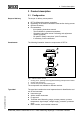
3 Product description l l Hardware and software version Article numbers, documentation 3.2 Principle of operation Application area DPT10 is a differential pressure transmitter for measurement of flow, level, differential pressure, density and interface. Measured products are gases, vapours and liquids. Flow measurement + Q ~ ∆p p1 + – p2 Q Q ~ ∆p – p1 p2 Q 1 2 Fig.
3 Product description Level measurement – ∆p h= ρ g h – + + – + 2 1 3 Fig. 3: Level measurement with DPT10. Δp = differential pressure, ρ = density of the medium, g = acceleration of gravity 1 2 3 Basic version with effective pressure lines Version with flange isolating diaphragm Version with capillaries and cell isolating diaphragms Differential pressure measurement 2 + 1 Fig.
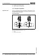
3 Product description Density measurement – = ∆p h g h + Fig. 5: Density measurement with DPT10, h = defined mounting distance, Δp = differential pressure, ρ = density of the medium, g = acceleration of gravity 1 DPT10 Interface measurement – 2 + h 3 1 Fig. 6: Interface measurement with DPT10 1 2 3 Functional principle DPT10 Liquid with highest density Liquid with lowest density A metallic measuring cell is used as sensor element.
3 Product description The configuration of the measuring cells differs depending on the measuring range: 1 2 p1 3 4 p2 5 Fig. 7: Metallic measuring cell 10 mbar and 30 mbar - p1 and p2 process pressures 1 2 3 4 5 Measuring element Silicone diaphragm Separating diaphragm Filling oil Integrated overvoltage arrester 1 p1 2 3 4 p2 Fig. 8: Metallic measuring cell from 100 mbar - p1 and p2 process pressures 1 2 3 4 Power supply and bus communication Power is supplied via the H1 Fieldbus.
3 Product description DD/CFF The DD (Device Descriptions) and CFF (capability files) necessary for planning and configuration of your FF (Foundation Fieldbus) communication network are available in the download area of the WIKA homepage www.wika.com under "Services". The appropriate certificates are also available there. A CD with the appropriate files and certificates can be ordered by phone from one of the WIKA agencies. The backlight of the indicating and adjustment module is powered by the sensor.
3 Product description Storage and transport temperature l l l l l Not in the open Dry and dust free Not exposed to corrosive media Protected against solar radiation Avoiding mechanical shock and vibration l Storage and transport temperature see chapter "Supplement Technical data - Ambient conditions" Relative humidity 20 … 85 % 37246-EN-100120 l Differential pressure transmitter DPT10 - metal measuring diaphragm • Foundation Fieldbus 13
4 Mounting 4 Mounting 4.1 General instructions Suitability for the process conditions Make sure that all parts of the instrument exposed to the process, in particular the sensor element, process seal and process fitting, are suitable for the existing process conditions. These include above all the process pressure, process temperature as well as the chemical properties of the medium. You can find the specifications in chapter "Technical data" or on the type label.
4 Mounting Effective pressure lines You find general recommendations for wiring of effective pressure lines in DIN 19210 "Effective pressure lines for flow systems" or the corresponding national or international standards. When wiring effective pressure lines outdoors, keep in mind to use a suitable antifreeze, e.g. by using tube heat tracing. Wire effective pressure lines with a monotonic decrease of at least 10 %.
4 Mounting 4.3 Measurement setup flow In gases à Mount DPT10 above the measurement loop so that condensate can drain off in the process cable. 1 2 3 + – 4 Fig.
4 Mounting 1 2 3 + 3 4 – 5 5 6 6 7 Fig. 11: Measurement setup, flow measurement in vapours 1 2 3 4 5 6 7 In liquids Condensate vessels Orifice or impact pressure probe Blocking valves DPT10 Precipitator Drain valves 3-fold valve block à Mount DPT10 below the measurement loop so that the effective pressure lines are always filled with liquid and gas bubbles can bubble up to the process line à For measurements in products with solid content such as e.g.
4 Mounting 1 2 + 2 3 – 4 4 5 5 6 Fig. 12: Measurement setup, flow measurement in liquids 1 2 3 4 5 6 Orifice or impact pressure probe Blocking valves DPT10 Precipitator Drain valves 3-fold valve block 4.
4 Mounting à For measurements in products with solid content such as e.g. dirty liquids, the installation of separators and drain valves is recommended to enable collection and removal of debris and sediment. patm + min. patm 1 2 4 5 3 Fig.
4 Mounting In closed vessels with effective pressure lines à Mount DPT10 below the lower measurement connection so that the effective pressure lines are always filled with liquid à Connect minus side always above the max. level à For measurements in products with solid content such as e.g. dirty liquids, the installation of separators and drain valves is recommended to enable collection and removal of debris and sediment. max. – min. + 1 1 2 3 3 4 4 5 Fig.
4 Mounting 1 – max. min. 2 + – + 3 4 Fig. 16: Measurement setup, level measurement in closed vessel 1 2 3 4 In closed vessels with bilateral pressure transmitter Blocking valve Precipitator Drain valve DPT10 à Mount DPT10 below the lower isolating diaphragm à The ambient temperature should be the same for both capillaries Information: Level measurement is only ensured between the upper edge of the lower and the lower edge of the upper pressure transmitter. – max. 1 min.
4 Mounting à Connect minus side always above the max. level à The condensate vessel ensures a constant pressure on the minus side à For measurements in products with solid content such as e.g. dirty liquids, the installation of separators and drain valves is recommended to enable collection and removal of debris and sediment. – 1 max. 2 min. + 2 3 4 5 5 6 Fig.
4 Mounting – max. 1 2 min. 3 + – + 5 4 Fig. 19: Measurement setup in closed vessel with superimposed steam 1 2 3 4 5 Condensate vessel Blocking valve Precipitator Drain valve DPT10 4.5 Measurement setup density and interface Density and interface measurement are carried out in level measurement mode.
4 Mounting Interface measurement à Mount DPT10 below the lower isolating diaphragm à The ambient temperature should be the same for both capillaries Information: An interface measurement is only possible if the densities of the two media remain the same and the interface is between the two measurement points. The total level must be above the upper measurement point. 0,3 m 0,8 1,0 – + 1 Fig. 21: Measurement setup with interface measurement. Min. adjustment with filling complete with density 0.
4 Mounting 4.6 Measurement setup differential pressure In gases and vapours à Mount DPT10 above the measurement loop so that condensate can drain off in the process cable. 1 2 + 3 3 4 Fig. 22: Measurement setup, differential pressure measurement in gases and vapours 1 2 3 4 In liquids DPT10 3-fold valve block Blocking valves E.g.
4 Mounting 1 2 2 – + 3 4 4 5 5 6 Fig. 23: Measurement setup, flow measurement in liquids 1 2 3 4 5 6 In gases, vapours and liquids E.g. filter Blocking valves DPT10 Precipitator Drain valves 3-fold valve block à Mount isolating diaphragm with capillaries on top or laterally on the pipeline à In vacuum applications: Mount DPT10 below the measurement loop à The ambient temperature should be the same for both capillaries 2 1 2 – + 3 4 1 2 3 4 26 Isolating diaphragm with bolting Capillaries E.
4 Mounting 4.7 Mounting arrangement and connection valve block Mounting arrangement The following illustration shows the elements for a tube mounting and an example for a mounting arrangement with valve block. 1 2 3 4 5 + – 6 7 8 9 Fig.
4 Mounting Connection valve block The following illustration shows the connection of a 5-fold valve block. A 7 8 9 A: 3 5 1 4 2 3 6 4 5 1 7 9 8 2 6 Fig.
4 Mounting 8 9 Oval flange adapter Fixing screws 4.8 External housing Wall mounting 1 Mark the holes according to the following drilling template 2 Depending on the mounting surface, fasten the wall mounting plate with 4 screws 90 mm (3.54") 70 mm (2.76") 3 mm (0.12") 8 mm (0.32") 93 mm (3.66") 110 mm (4.33") mm ,5 ") R3 0.14 ( Fig. 27: Drilling template - wall mounting plate Mount the wall mounting plate so that the cable entry of the socket housing points downward.
5 Connecting to power supply 5 Connecting to power supply 5.
5 Connecting to power supply Select connection cable for Ex applications Take note of the corresponding installation regulations for Ex applications. In particular, make sure that no potential equalisation currents flow over the cable screen. In case of grounding on both sides this can be achieved by the use of a capacitor or a separate potential equalisation. 5.
5 Connecting to power supply The electrical connection is finished. Fig.
5 Connecting to power supply 2 Remove the housing socket from the mounting plate 3 1 2 Fig. 29: Components of the external housing 1 2 3 Screw Wall mounting plate Cable gland 3 Loop the connection cable through the cable entry on the housing base1) Information: The cable gland can be mounted in three positions each displaced by 90°. Simply exchange the cable gland against the blind plug in the suitable thread opening.
5 Connecting to power supply 5.3 Single chamber housing The following illustrations apply to the non-Ex as well as to the Ex-ia version. Electronics and connection compartment Typ: Bus Display Sim. 5 I²C 1 2 5 6 7 8 1 2 4 3 Fig.
5 Connecting to power supply 5.4 Wiring plan, double chamber housing The following illustrations apply to the non-Ex as well as to the Ex-ia version. Electronics compartment 1 Typ: Display Sim. Bus I²C 1 2 2 5 6 7 8 3 Fig.
5 Connecting to power supply Display Connection compartment 1 3 1 I²C 2 2 Fig. 33: Connection compartment double chamber housing 1 2 3 Plug connector for service Ground terminal for connection of the cable screen Spring-loaded terminals for voltage supply Wiring plan I2C 1 2 1 Fig.
5 Connecting to power supply 5.5 Double chamber housing Ex d Electronics compartment 1 Typ: 2 Display Sim. Bus I²C 1 2 5 6 7 8 3 Fig. 35: Electronics compartment, double chamber housing 1 2 3 Simulation switch ("on" = mode for simulation release) Connection for service Internal connection cable to the connection compartment Connection compartment 1 1 2 2 37246-EN-100120 Fig.
5 Connecting to power supply Wiring plan 1 2 1 Fig. 37: Wiring plan with double chamber housing Ex d 1 Voltage supply/Signal output 5.6 Version IP 66/IP 68, 1 bar Wire assignment, connection cable + 1 2 Fig.
5 Connecting to power supply 5.7 External housing with version IP 68 Electronics and connection compartment Typ: 6 5 Display Sim. Bus I²C 1 2 1 5 6 7 8 2 4 3 Fig.
5 Connecting to power supply Terminal compartment for sensor connection 1 2 3 4 1 2 3 4 5 Fig. 40: Connection of the sensor in the housing socket 1 2 3 4 5 Brown Blue Yellow White Shielding Wiring plan external electronics Display I2C 1 2 5 6 7 8 1 Fig. 41: Wiring plan external electronics 1 Voltage supply 5.8 Switch on phase 40 After DPT10 is connected to voltage supply or after voltage recurrence, the instrument carries out a self-check for approx. 30 seconds.
5 Connecting to power supply l l l Internal check of the electronics Indication of the instrument type, the firmware as well as the sensor TAGs (sensor designation) Status byte goes briefly to fault value 37246-EN-100120 Then the current measured value will be displayed and the corresponding digital output signal will be outputted to the cable.2) 2) The values correspond to the actual measured level as well as to the settings already carried out, e.g. default setting.
6 Adjustment with the indicating and adjustment module 6 Adjustment with the indicating and adjustment module 6.1 Short description Function/Configuration The indicating and adjustment module is used for measured value display, adjustment and diagnosis.
6 Adjustment with the indicating and adjustment module Fig. 42: Insert indicating and adjustment module 37246-EN-100120 Note: If you intend to retrofit the instrument with an indicating and adjustment module for continuous measured value indication, a higher cover with an inspection glass is required.
6 Adjustment with the indicating and adjustment module 6.3 Adjustment system 2 1 1.1 3 Fig.
6 Adjustment with the indicating and adjustment module 6.4 Parameter description Introduction DPT10 has general adjustment parameters which are also used for other measuring principles as well as instrument-specific adjustment parameters. The general adjustment parameters are described in the operating instructions manual "Indicating and adjustment module". The instrument-specific adjustment parameters are described in this chapter.
6 Adjustment with the indicating and adjustment module Unit of measurement In this menu item you select the adjustment unit as well as the unit for the temperature indication in the display. To select the adjustment unit (in the example switching over from mbar to bar), proceed as follows: 1 ▶ 2 Push the [OK] button in the measured value display, the menu overview is displayed.
6 Adjustment with the indicating and adjustment module Unit of measurement Density 0001000 kg/dm³ 6 Enter the requested density value with [->] and [+], confirm with [OK] and move to position correction with [->]. The adjustment unit is thus switched over from bar to m. Proceed as follows to select the temperature unit: à Activate the selection with [OK] and select "Temperature unit with [->]. à Activate the selection with [OK] and select the requested unit with [->] (e.g. °F). à Confirm with [OK].
6 Adjustment with the indicating and adjustment module If a known value should be taken over as position correction which is not the current value, then you have to select the function "Edit" and enter the requested value. Zero adjustment with differential pressure In this menu item, the min. differential pressure is entered. Proceed as follows: 1 Edit the bar value in the menu item "zero" with [OK]. Zero adjustment 0.00 % = 0.0000 bar 0.0000 bar DP 2 Set the requested value with [+] and [->].
6 Adjustment with the indicating and adjustment module Min. adjustment with level Proceed as follows: 1 Edit the % value in the menu item "Min. adjustment" with [OK]. Min. adjustment 0.00 % = 0.0000 bar 0.0000 bar 2 Set the requested value with [+] and [->]. 3 Confirm with [OK] and edit the requested bar value. 4 Set the requested bar value with [+] and [->]. 5 Confirm with [OK] and move to max. adjustment with [->].
6 Adjustment with the indicating and adjustment module Information: When the instrument is not yet adjusted, then the display pressure for 100 % corresponds to the nominal measuring range of the sensor (in the above example 500 mbar). 2 Set the requested mbar value with [->] and [OK]. 3 Confirm with [OK] and move to the menu overview with [ESC]. For an adjustment with flow, simply enter the actual measured value indicated at the bottom of the display. The max. adjustment is finished.
6 Adjustment with the indicating and adjustment module Part sum counter 0.0000 1000 gal Modify settings? 2 Activate the function "Modify settings?" with [OK]. Part sum counter ▶ 3 Effective pressure transmitter Unit Confirm with [OK] "Effective pressure transmitter". Part sum counter ▶ ▶ Mass flow Volume flow Without unit 4 Select the requested variable with [->] and confirm with [OK]. 5 Select calibration unit of the effective pressure transmitter with [>], for example m3/s and confirm with [OK].
6 Adjustment with the indicating and adjustment module l l l l l l Linearisation curve Leak volume suppression Sensor-TAG Displayed value Display unit Language The following safety-relevant data are not read out or written: l PIN Copy sensor data Copy sensor data? Reset Basic adjustment The reset "Basic adjustment" resets the following menu items to the reset values (see chart): Menu section Menu item Reset value Basic settings Unit of measurement bar Temperature unit °C Zero/Min.
6 Adjustment with the indicating and adjustment module Menu section Menu item Reset value Service Language no reset Pointer The min. and max. temperature or pressure values are each reset to the actual value. Totalizer The total and part sum counter are reset to zero. Additional adjustment and diagnosis options such as e.g. scaling, simulation or trend curve presentation are shown in the following menu schematic.
6 Adjustment with the indicating and adjustment module 6.5 Menu schematic Information: Depending on the version and application, the highlighted menu windows are not always available. Basic adjustment differential pressure ▶ 1 Basic adjustment Display Diagnostics Service Info Application 1.1 Differential pressure ▼ Span 100.00 % = 0.5000 bar 0.0000 bar 1.4 Unit Unit of measurement bar ▼ Temperature unit °C ▼ 1.1 Damping 1.5 ▶ DP 1s Position correction Offset = -0.0035 bar 0.0000 bar 1.
6 Adjustment with the indicating and adjustment module Basic setting level ▶ Basic adjustment Display Diagnostics Service Info Application 1 1.1 Level ▼ Max. adjustment 100.00 % = 0.5000 bar 0.0000 bar 1.4 Unit Unit of measurement bar ▼ Temperature unit °C ▼ 1.1 Damping 1.5 ▶ 1s Position correction Offset = -0.0035 bar 0.0000 bar 1.2 Linearisation curve linear Cylindrical tank Spherical tank User programmable 1.6 Lighting 2.4 DP Min. adjustment 000.0 % = 0.0000 bar 0.0000 bar 1.
6 Adjustment with the indicating and adjustment module Service ▶ Basic adjustment Display Diagnostics Service Info Simulation 4 4.2 Start simulation ▼ Reset 4.3 Select reset ▼ Language 4.4 Deutsch ▼ Copy sensor data 4.7 Copy sensor data? 4.8 PIN Enable? Info ▶ Basic adjustment Display Diagnostics Service Info Instrument type 5 5.1 Date of manufacture 23rd October 2009 5.2 Last change using PC 23rd October 2009 Serial number 12345678 5.3 Sensor characteristics 5.
6 Adjustment with the indicating and adjustment module 6.6 Saving the parameter adjustment data It is recommended noting the adjusted data, e.g. in this operating instructions manual and archive them afterwards. They are hence available for multiple use or service purposes. If DPT10 is equipped with an indicating and adjustment module, the most important data can be read out of the sensor into indicating and adjustment module.
7 Setup with the adjustment program AMS™ 7 Setup with the adjustment program AMS™ 7.1 Parameter adjustment with AMS™ For WIKA sensors, instrument descriptions for the adjustment program AMS™ are available as DD. The instrument descriptions are already implemented in the current version of AMS™. For older versions of AMS™, a free-of-charge download is available via Internet. Go via www.WIKA.com and "Downloads" to the item "Software".
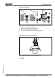
8 Set up 8 Set up 8.1 Select the mode The following modes can be adjusted on DPT10: l l l Flow measurement Level measurement Differential pressure measurement 8.2 Flow measurement Instructions In flow measurement, normally DPT10 is used without isolating diaphragm. Before adjusting DPT10, you have to clean the effective pressure lines and the instrument must be filled with the medium. Installation for gases 6 7 I + – 3 II 2 4 + A B Fig.
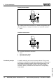
8 Set up Installation for liquids A + B 6 7 + – I III II 1 III 3 2 4 5 Fig. 45: Preferred installation for liquids I DPT10 II 3-fold valve block III Precipitator 1.5 Drain valves 2.4 Inlet valves 3 Breather valve 6.7 Vent valves on DPT10 A, B Blocking valves Prepare the adjustment Proceed as follows: 1 2 Close valve 3 Fill measuring system with medium.
8 Set up 4 Carry out a position correction if the following conditions apply. If the conditions are not fulfilled, then carry out the position correction after step 6. Conditions: The process cannot be sealed off. The pressure extraction points (A and B) are at the same geodesic height.
8 Set up Installation for open vessels Fig. 46: Preferred installation for open vessels I II 1 6.7 A Prepare the adjustment DPT10 Precipitator Drain valve Vent valves on DPT10 Blocking valve Proceed as follows: 1 2 Fill the vessel to just over the lower tap. Fill measuring system with medium. Open valve A: Medium flows in. 3 Vent instrument Briefly open valve 6, then close it: Fill the measuring instrument completely with the medium and remove air.
8 Set up Installation for closed vessels B + A 6 7 + – I II III III 3 2 4 1 5 Fig.
8 Set up Installation for closed vessels with steam layer IV B + A 6 7 I + II III – III 3 2 4 1 5 Fig.
8 Set up Now: Valve 3, 6 and 7 are closed Valves 2, 4, A and B are open. Then carry out adjustment, see chapter "Set parameters". 8.4 Density and interface measurement For density and interface measurements, DPT10 with bilateral isolating diaphragm CSB is used. DPT10 in this version is immediately ready for operation. 8.5 Differential pressure measurement Instructions For differential pressure measurements, DPT10 without isolating diaphragm or with bilateral isolating diaphragm CSB is used.
8 Set up Installation for liquids A + B 6 7 + – I III II 1 III 3 2 4 5 Fig. 50: Preferred installation for liquids I DPT10 II 3-fold valve block III Precipitator 1.5 Drain valves 2.4 Inlet valves 3 Breather valve 6, 7 Vent valves on DPT10 A, B Blocking valves Prepare the adjustment Proceed as follows: 1 2 Close valve 3 Fill measuring system with medium. Open valves A, B, 2, 4: Medium flows in.
8 Set up Open valve 4: Connect minus side Now: Valves 1, 3, 5, 6 and 7 are closed6) Valves 2 and 4 open Valves A and B open (if available) 37246-EN-100120 Then carry out adjustment, see chapter "Set parameters". 6) Valves 1, 3, 5: Configuration with 5 valves.
9 Maintenance and fault rectification 9 Maintenance and fault rectification 9.1 Maintain Maintenance When the instrument is used properly, no special maintenance is required in normal operation. In some applications, product buildup on the separating diaphragms can influence the measuring result. Depending on the sensor and application, take precautions to ensure that heavy buildup, and especially a hardening thereof, is avoided. 9.
9 Maintenance and fault rectification In Ex applications, the regulations for the wiring of intrinsically safe circuits must be observed.
10 Dismounting 10 Dismounting 10.1 Dismounting steps Warning: Before dismounting, be aware of dangerous process conditions such as e.g. pressure in the vessel, high temperatures, corrosive or toxic products etc. Take note of chapters "Mounting" and "Connecting to power supply" and carry out the listed steps in reverse order. 10.2 Dispose The instrument consists of materials which can be recycled by specialised recycling companies.
11 Supplement 11 Supplement 11.1 Technical data General data Pressure type Differential pressure Measuring principle Piezoresistive Communication interface I²C bus Materials and weights Material 316L corresponds to stainless steel 1.4404 or 1.
11 Supplement Max. torque screws mounting strap 30 Nm Max. torque screws socket external housing 5 Nm (3.688 lbf ft) Weight approx. 4.2 … 4.5 kg (9.26 … 9.92 lbs), depending on process fitting Output variable Output - Signal - digital output signal, Foundation Fieldbus protocol according to IEC 61158-2 Physical layer Channel Numbers - Channel 1 Primary value - Channel 2 Secondary value 1 - Channel 3 Secondary value 2 - Channel 4 Temperature value Transmission rate 31.
11 Supplement Version, nominal measuring range Dead time t1 Time constant t2 Isolating diaphragm version, all nominal measuring ranges Depending on the isolating diaphragm Depending on the isolating diaphragm Response time with Foundation Fieldbus - cyclically approx. - 10 ms 50 ms acyclically approx.
11 Supplement Characteristics linear Position of the measuring cell constant, in the range: horizontal ±1° Span based on the zero point Diaphragm material 316L, Alloy C276, gold rhodium plated, Monel Filling oil Silicone oil Material, lateral flanges 316L Influence of the installation position basic version ≤ 4 mbar9)10) A position-dependent zero-point shift can be corrected (see also chapter "General installation instructions" and "Installation instructions, isolating diaphragm systems").
11 Supplement ±(0.0015 % x TD + 0.053) of the set span + influence of the isolating diaphragm Influence of the product or ambient temperature Applies to instruments in basic version with digital signal output (HART, Profibus PA, Foundation Fieldbus) as well as to instruments with analogue current output 4 … 20 mA. Specifications refer to the set span. Turn down (TD) = nominal measuring range/set span.
11 Supplement Measuring cell 3 bar 16 bar 40 bar Influence of the system pressure to the span ±0.14 % of URL/7 bar ±0.14 % of URL/70 bar ±0.14 % of URL/70 bar Tantalum diaphragm Measuring cell 10 mbar 30 mbar 100 mbar 500 mbar Influence of the system pressure to the zero point ±0.28 % of URL/ 7 bar ±0.70 % of URL/ 70 bar ±0.42 % of URL/ 70 bar ±0.14 % of URL/ 70 bar Influence of the system pressure to the span ±0.28 % of URL/ 7 bar ±0.70 % of URL/ 70 bar ±0.42 % of URL/ 70 bar ±0.
11 Supplement Diaphragm material Tantalum Measuring range Total Error from 500 mbar 0,20 % of the measuring range final value < 500 mbar 0.48 % of the measuring range end value/year from 500 mbar 0.
11 Supplement With effective pressure lines longer than 100 mm, process fitting steel C22.
11 Supplement Electromechanical data - version IP 66/IP 67 Cable entry/plug22) - Single chamber housing l 1 x cable gland M20 x 1.5 (cable: ø 5 … 9 mm), 1 x blind stopper M20 x 1.5 or: l 1 x closing cap ½ NPT, 1 x blind plug ½ NPT or: - Double chamber housing l 1 x plug (depending on the version), 1 x blind stopper M20 x 1.5 l 1 x cable entry M20 x 1.5 (cable: ø 5 … 9 mm), 1 x blind stopper M20 x 1.
11 Supplement - Colour - standard PE Black - Colour - standard PUR Blue - Colour - Ex-version Blue Electromechanical data - version IP 66/IP 68 with external electronics Connection cable between IP 68 instrument and external housing: - Configuration Four wires, screen braiding, inner cover, screen braiding, outer cover - Wire cross-section 0.5 mm² (AWG 20) - Standard length 5 m (16.40 ft) - Max. length 25 m (82.02 ft) - Min. bending radius at 25 °C/77 °F 25 mm (0.
11 Supplement Operating voltage with lighted indicating and adjustment module24) - Non-Ex instrument 12 … 32 V DC25) - EEx-ia instrument 12 … 24 V DC26) - EEx-ia instrument 12 … 32 V DC27) Power supply by/max. number of sensors - H1 power supply max. 32 (max.
11 Supplement 11.2 Information on Foundation Fieldbus Block diagram, measured value processing The following illustration shows the Transducer Block and Function block in simplified form.
11 Supplement l l l l l l l l l l l l - l l l 37246-EN-100120 l - primary_value Process Value after min/max-adjustment and linearization. Selected as input to AIFB by setting 'Channel' = 1. Unit derives from 'Primary_value_unit' primary_value_unit - Unit code of 'Primary_value' % secondary_value_1 Process pressure. Selected as input to AIFB by setting 'Channel' = 2.
11 Supplement - l l l l l l l l l l l l - 84 SUB_DEVICE_NUMBER SENSOR_ELEMENT_TYPE 0: "non-specific" display_source_selector - Selects the type of value that is displayed on the indication-/adjustement-module "0: ""Physical value"" 1: ""Percent value"" 2: ""Lin percent value"" 6: ""Out(AI1)"" 7: ""Level"" 8: ""Out(AI2)"" 9: ""Out(AI3)""" max_peak_sensor_value - Holds the maximum sensor value. Write access resets to current value. Unit derives from 'Sensor_range.
11 Supplement l l min_peak_temperature_value - Holds the minimum process temperature. Write access resets to current value. Unit derives from 'Temperature.unit' Write access resets to current value 37246-EN-100120 - max_peak_temperature_value - Holds the maximum process temperature. Write access resets to current value. Unit derives from 'Temperature.
11 Supplement 11.3 Dimensions Plastic housing ~ 69 mm (2.72") ø 77 mm (3.03") ~ 87 mm (3.43") 112 mm (4.41") 120 mm (4.72") ø 84 mm (3.31") M20x1,5/ ½ NPT M20x1,5/ ½ NPT 1 1 2 2 Single chamber version Double chamber version Aluminium housing ~ 87 mm (3.43") ~ 116 mm (4.57") ø 84 mm (3.31") M20x1,5 M20x1,5/ ½ NPT 1 1 2 120 mm (4.72") 116 mm (4.57") ø 84 mm (3.
11 Supplement Aluminium housing in protection rating IP 66/IP 68 (1 bar) ~ 105mm (4 9/64") ø 84mm (3 5/16") ~ 150mm (5 29/32") ø 84mm (3 5/16") M20x1,5 M20x1,5 M20x1,5/ ½ NPT 1 1 4 120mm (4 23/32") 116mm (4 9/16") M16x1,5 2 Single chamber version, Aluminium Double chamber housing Aluminium Version IP 68 with external electronics ø 55 mm (2.17") + – 59 mm (2.32") 93 mm (3.66") 103 mm (4.06") 68,3 mm (2.69") 1 90 mm (3.54") 110 mm (4.33") 115 mm (4.53") ~ 66 mm (2.6") ø 55 mm (2.
11 Supplement 41,3 mm (1.63") 85 mm (3.35") 134,5 mm (5.3") Oval flange, connection ¼-18 NPT or RC ¼ 7/16-20 UNF M 10 + – 1/4-18 NPT RC1/4 106 mm (4.17") 7/16-20 UNF M 10 (M12) 41,3 mm (1.63") 72 mm (2.84") 128 mm (5.04") 54 mm (2.13") 100 mm (3.94") + – 1/4-18 NPT RC1/4 100 mm (3.94") 54 mm (2.13") 98 mm (3.94") Fig. 58: Top: 10 mbar and 30 mbar measuring cell. Bottom: Measuring cell ≥ 100 mbar Connection Fastening Material Equipment B 1/4-18 NPT IEC 61518 7/16-20 UNF Steel C 22.
11 Supplement Version Connection Fastening Material Equipment U RC 1/4 7/16-20 UNF AISI 316L incl. 2 vent valves (316L) 1 1/4-18 NPT IEC 61518 PN 160: M10, PN 420: M12 Steel C 22.8 incl. 2 vent valves (316L) 2 1/4-18 NPT IEC 61518 PN 160: M10, PN 420: M12 AISI 316L incl. 2 vent valves (316L) 3 1/4-18 NPT IEC 61518 PN 160: M10, PN 420: M12 Alloy C276 without valves/closing screws + – 1/4-18 NPT RC1/4 54 mm (2.13") 100 mm (3.94") 106 mm (4.17") 42 mm (1.65") 41,3 mm (1.
11 Supplement Version Connection Fastening Material Equipment V RC 1/4 7/16-20 UNF AISI 316L incl. 4 closing screws (AISI 316L) and 2 ventilation valves 1 + – 54 mm (2.13") 98 mm (3.94") 7/16-20 UNF M 10 (M12) 41,3 mm (1.63") 128 mm (5.04") 72 mm (2.84") Oval flange, prepared for isolating diaphragm connection + – M6 2 3 54 mm (2.13") 98 mm (3.94") Fig. 60: left: Process fitting DPT10 prepared for isolating diaphragm connection.
Index INDEX A M Adjustment - Unit 46 - with differential pressure 48 - with ow 49 - with level 49 Application area - Density measurement 10 - Differential pressure measurement 9 - Flow measurement 8 - Interface measurement 10 - Level measurement 9 Maintenance 68 Mounting arrangement 27 Mounting position 14 C Connection compartment 37 Connection compartment double chamber housing 36 D Density measurement 23 Differential pressure measurement - In gases and vapours 25 - In liquids 25 E Electronics and c
Printing date:: WIKA Alexander Wiegand SE & Co. KG Alexander-Wiegand-Straße 30 63911 Klingenberg/Germany Phone +49 9372 132295 Fax +49 9372 132706 e-mail: support-tronic@wika.de www.wika.de All statements concerning scope of delivery, application, practical use and operating conditions of the sensors and processing systems correspond to the information available at the time of printing.