Operating Instructions Indicating and adjustment module for IPT-1* sensors
Contents Contents 1 About this document 1.1 1.2 1.3 2 . . . . . . . . .. .. .. .. .. .. .. .. 4 4 4 4 4 4 5 5 . . . . . . . . . . . . . . . . . . . . . . . . .. .. .. .. 6 7 7 8 Mounting steps. . . . . . . . . . . . . . . . . . . . . . . . . . . . . 9 Configuration . . . . . . . . . . . . . . . Principle of operation . . . . . . . . . Operation. . . . . . . . . . . . . . . . . . Packaging, transport and storage . . . . . . . . . . . . . . . . . . . . . . . . . . . . .. .. .. .. .. ..
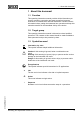
1 About this document 1 About this document 1.1 Function This operating instructions manual provides all the information you need for mounting, connection and setup as well as important instructions for maintenance and fault rectification. Please read this information before putting the instrument into operation and keep this manual accessible in the immediate vicinity of the device. 1.2 Target group This operating instructions manual is directed to trained qualified personnel.
2 For your safety 2 For your safety 2.1 Authorised personnel All operations described in this operating instructions manual must be carried out only by trained specialist personnel authorised by the plant operator. During work on and with the device the required personal protective equipment must always be worn. 2.2 Appropriate use The pluggable indicating and adjustment module is used for remote measured value indication and parameter adjustment for IPT-1* pressure transmitters. 2.
2 For your safety 2.7 Compatibility according to NAMUR NE 53 With respect to compatibility, NAMUR recommendation NE 53 is met. The parameter adjustment of the basic sensor functions is independent of the software version. The range of available functions depends on the respective software version of the individual components. 2.8 Safety instructions for Ex areas 31549-EN-081211 Please note the Ex-specific safety information for installation and operation in Ex areas.
3 Product description 3 Product description 3.1 Configuration Scope of delivery The scope of delivery encompasses: l l Equipment Indicating and adjustment module Documentation - this operating instructions manual The indicating and adjustment module is equipped with a display with full-dot matrix as well as four keys for adjustment. An integrated backlight can be switched via the adjustment menu.
3 Product description 1 2 Fig. 2: Rear of the indicating/adjustment module 1 Integrated seal ring 2 Gold plated contact paths 3.2 Principle of operation Application area The indicating and adjustment module is used for measured value indication, adjustment, and diagnostics for the following WIKA® sensors: l l l IPT-10 vers. 2.0 (ceramic sensor) IPT-1* vers. 3.0 (metallic sensor) IPT-11 vers. 4.
3 Product description 3.4 Packaging, transport and storage Packaging Your instrument was protected by packaging during transport. Its capacity to handle normal loads during transport is assured by a test according to DIN EN 24180. The packaging of standard instruments consists of environmentfriendly, recyclable cardboard. For special versions, PE foam or PE foil is also used. Dispose of the packaging material via specialised recycling companies.
4 Mounting 4 Mounting 4.1 Mounting steps Mount/Dismount indicating and adjustment module The indicating and adjustment module can be inserted or removed at any time. It is not necessary to interrupt the voltage supply. For mounting, proceed as follows: 1 Unscrew the housing cover 2 Place the indicating/adjustment module in the requested position on the electronics Information: Four different positions are possible, each displaced by 90°. 31549-EN-081211 Fig.
4 Mounting Dismounting is carried out in reverse order.
5 Set up 5 Set up 5.1 Adjustment system 2 1 1.1 3 Key functions 31549-EN-081211 Adjustment system Fig.
5 Set up 5.2 General functions Introduction IPT-1* pressure transmitters have various functions. Hence they can be adapted to the respective application. Some of these functions are sensor-specific. These are described in the operating instructions manual of the corresponding sensor. Other functions, however, have a general character, i.e. they are available in different sensors. The general functions are described in this paragraph.
5 Set up The linearization curve creates a correlation between height and volume. It takes into account the vessel geometry for the displayed measured value and current output. Factory setting is linear. Linearisation curve linear Edit sensor TAG In the menu item "Sensor-TAG" you edit a 12-digit measurement loop name. An unambiguous designation can hence be assigned to the sensor, e.g. the measurement loop name or the tank or product designation.
5 Set up l Min. and max. temperature2) Pointer Sensor status In this menu item, the device status is displayed. If the sensor detects a fault, "OK" will be displayed. If a fault is detected, a flashing failure message is outputted sensor-specifically, e.g. "E013". The fault is also displayed in clear text, e.g. "No measurement value". Information: The fault message as well as the clear text indication are also carried out in the measured value display. Meas.
5 Set up 1 Push [OK] 2 Select the requested simulation variable with [->] and confirm with [OK] 3 Set the requested value with [+] and [->]. 4 Push [OK] The simulation is now running, with 4 … 20 mA/HART a current is outputted and with Profibus PA or Foundation Fieldbus a digital value. How to interrupt the simulation: à Push [ESC] Information: The simulation is terminated automatically 10 minutes after the last key has been pushed.
5 Set up Language The sensor is already set to the ordered national language. In this menu item you can change the language. The following languages are available, e.g. in software version 3.
5 Set up PIN In this menu item, the PIN is activated/deactivated permanently. Entering a 4-digit PIN protects the sensor data against unauthorized access and unintentional modifications. If the PIN is activated permanently, it can be deactivated temporarily (i.e. for approx. 60 min.) in any menu item. The instrument is delivered with the PIN set to 0000.
5 Set up l Sensor details, e.g. approval, process fitting, seal, measuring cell, measuring range, electronics, housing, cable entry, plug, cable length etc. Sensor characteristics Display now? 5.3 Special functions - 4 … 20 mA/HART Introduction The 4 … 20 mA/HART special functions are briefly described in this paragraph. The respective range of functions of the indicating and adjustment module is determined by the sensor and the sensor software version.
5 Set up Display unit Volume l Scaling 0 % = 0.0 l 100 % = 100.0 l Menu section, service Current output In the menu item "Current output" you determine the behaviour of the current output during operation and in case of failure. The following options are available: Current output Characteristics curve 4 … 20 mA 20 … 4 mA Failure mode3) Hold value 20.5 mA 22 mA < 3.6 mA Min. current4) 3.8 mA 4 mA Max. current5) 20 mA 20.5 mA The values in bold font represent the data of the factory setting.
5 Set up l l In the menu item "Failure mode" under "Current output", the parameters "Hold value" and "20.5 mA" are blocked In the menu item "HART mode", the function "Multidrop" is blocked Note: For such applications, it is absolutely necessary to take note of "Safety Manual". HART mode HART offers standard and multidrop mode. The mode standard with the fixed address 0 means output of the measured value as 4 … 20 mA signal. In Multidrop mode, up to 15 sensors can be operated on one two-wire cable.
5 Set up Channel The channel is the input selector switch for function block (FB) of the sensor. Within the function block, additional scalings (Out-Scale) are carried out. In this menu item, the value fir the function block is selected: l SV1 (Secondary Value 1): - Pressure or height l SV2 (Secondary Value 2): - Percent l PV (Primary Value): - Linearised percentage value Channel PV lin.
5 Set up Determine Out-Scale Here, you determine the unit and scaling for PA-Out. These settings also apply to the values displayed on the indicating and adjustment module if in the menu item "Displayed value" PA-Out was selected.7) In the menu item "PV-Out-Scale", the requested numerical value with decimal point is entered for 0 % and 100 % of the measured value.
5 Set up 5.5 Menu schematic Information: Depending on the version and application, the highlighted menu windows are not always available. Basic adjustment ▶ Basic adjustment Display Diagnostics Service Info 1 Unit Unit of measurement bar▼ Temperature unit °C▼ 1.1 Damping 1.5 Position correction Offset = 0.2 mbar 0000 mbar 1.2 Linearisation curve 1.6 P linear ▼ 1s Min. adjustment 000.0 % = 0.0 mbar 0.0 mbar 1.3 Sensor-TAG 1.7 Max. adjustment 100.00 % = 100.00 mbar 0.0 mbar 1.
5 Set up Diagnostics ▶ Basic adjustment Display Diagnostics Service Info Pointer p-min.: -5.8 mbar p-max.: 167.5 mbar T-min.: -12.5 °C T-max.: +85.5 °C 3 3.1 Sensor status 3.2 OK Trend curve 3.3.1 Start trend curve? Service ▶ Basic adjustment Display Diagnostics Service Info Current output 4 4.1 Output mode: 4-20 mA ▼ Fail.mode: < 3.6 mA ▼ Min. current: 3.8 mA ▼ max. current: 20.5 mA ▼ SIL 4.2 Start simulation ▼ 4.5 Deactivated!▼ Application Simulation HART mode Reset 4.
31549-EN-081211 5 Set up Indicating and adjustment module for IPT-1* sensors 25
5 Set up 5.6 Menu schematic Information: Depending on the version and application, the highlighted menu windows are not always available. Basic adjustment ▶ Basic adjustment Display Diagnostics Service Info Sensor address 1 1.1 126 Max. adjustment 100.00 % = 100.00 mbar 0.0 mbar 1.4 Unit Unit of measurement bar▼ Temperature unit °C▼ 1.1 Damping 1.5 Position correction Offset = 0.2 mbar 0000 mbar 1.2 Linearisation curve 1.6 P linear ▼ 0s Min. adjustment 000.0 % = 0.0 mbar 0.0 mbar 1.
5 Set up Service ▶ Basic adjustment Display Diagnostics Service Info Additional PA value 4 4.1 Secondary Value 1 Reset 4.2 Volume l 4.3 Select reset ▼ Application Out-Scale-Unit Language 4.6 Deutsch PA-Out-Scale 100.00 lin % = 0.0 l 0.00 lin % = 100.0 l 4.3 Copy sensor data 4.7 Simulation 4.2 Start simulation ▼ Copy sensor data? PIN 4.8 Enable? 4.9 Level ▼ Info ▶ Basic adjustment Display Diagnostics Service Info Sensor type 5.1 Date of manufacture e.g. 16.
5 Set up 5.7 Menu schematic Information: Depending on the version and application, the highlighted menu windows are not always available. Basic adjustment ▶ Basic adjustment Display Diagnostics Service Info 1 Unit Unit of measurement bar▼ Temperature unit °C▼ 1.1 Damping 1.5 Position correction Offset = 0.2 mbar 0000 mbar 1.2 Linearisation curve 1.6 P linear ▼ 0s Min. adjustment 000.0 % = 0.0 mbar 0.0 mbar 1.3 Sensor-TAG 1.7 Max. adjustment 100.00 % = 100.00 mbar 0.0 mbar 1.
5 Set up Service ▶ Basic adjustment Display Diagnostics Service Info Simulation 4 4.2 Reset Start simulation ▼ PIN 4.3 Select reset ▼ 4.5 Enable? Application Language 4.3 Deutsch Copy sensor data 4.4 Copy sensor data? 4.6 Level Info ▶ Basic adjustment Display Diagnostics Service Info Device-ID 5 5.1 Sensor type 5.2 Sensor-TAG Serial number 12345678 Sensor characteristics Date of manufacture e.g. 16. May 2008 Software version e.g. 3.50 5.2 Last change using PC 5.3 e.g. 16.
6 Maintenance and fault rectification 6 Maintenance and fault rectification 6.1 Maintenance When used in the correct way, no special maintenance is required in normal operation. 6.2 Instrument repair You can download a return form (24 KB) in the Internet from our homepage www.wika.com under the item "Service".
7 Dismounting 7 Dismounting 7.1 Dismounting steps Warning: Before dismounting, be aware of dangerous process conditions such as e.g. pressure in the vessel, high temperatures, corrosive or toxic products etc. Take note of chapters "Mounting" and "Connecting to power supply" and carry out the listed steps in reverse order. 7.2 Disposal The indicating and adjustment module consists of materials which can recycled by specialised recycling companies.
8 Supplement 8 Supplement 8.1 Technical data General data Weight approx. 150 g (0.
8 Supplement 8.2 Dimensions Indicating and adjustment module 27,6mm (1 3/32") ø66,3mm (2 39/64") 45,1mm (1 25/32") 9,7mm (3/8") 31549-EN-081211 Fig.
8 Supplement 31549-EN-081211 34 Indicating and adjustment module for IPT-1* sensors
31549-EN-081211 8 Supplement Indicating and adjustment module for IPT-1* sensors 35
Printing date:: WIKA Alexander Wiegand GmbH & Co. KG Alexander-Wiegand-Straße 30 63911 Klingenberg/Germany Phone +49 9372 132295 Fax +49 9372 132706 e-mail: support-tronic@wika.de www.wika.de All statements concerning scope of delivery, application, practical use and operating conditions of the sensors and processing systems correspond to the information available at the time of printing.