
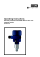
User guide

4 Mounting
4.1 General instructions
Make sure that all parts of the instrument in contact with the measured
product, especially the sensor element, process seal and pr ocess
fitting, are suitable for the existing process conditions such as process
pressure, process temperature as well as the chemical properties of
the medium.
You can find the specifications in chapter "Technical data" in the or on
the type label.
Select an installation position you can easily reach for mounting and
connecting as well as later retrofitting of an indicating and adjustment
module. The housing can be rotated by 330° without the use of any
tools. You can also install the indicating and adjustment module in four
different positions (each displaced by 90°).
Use the recommended cables (see chapter "Connecting to power
supply") and tighten the cable gland.
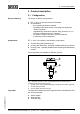
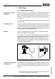
You can give your instrument additional protection against moisture
penetration by leading the connection cable downward in front of the
cable entry. Rain and condensation water can thus drain off. This
applies mainly to outdoor mounting as well as installation in areas
where high humidity is expected (e.g. through cleaning processes) or
on cooled or heated vessels.
Fig. 2: Measures against moisture penetration
The ventilation of the measuring cell is realised by a filter element in
the socket of the electronics housing. The ventilation of the electronics
housing is realised via an additional filter element around the cable
glands.
1)
1)
With previous instrument versions, ventilation and pressure compensation
were carried out together via a filter element.
Suitability for process
conditions
Mounting position
Moisture
Ventilation and pressure
compensation
10 Process pressure transmitter IPT-10 Vers. 2.0 - ceramic sensor • Profibus PA
4 Mounting
31541-EN-081211