
User guide

Contents
1 About this document
1.1 Function. . . . . . . . . . . . . . . . . . . . . . . . . . . . . . . . . .
4
1.2 Target group . . . . . . . . . . . . . . . . . . . . . . . . . . . . . .
4
1.3 Symbolism used. . . . . . . . . . . . . . . . . . . . . . . . . . . .
4
2 For your safety
2.1 Authorised personnel . . . . . . . . . . . . . . . . . . . . . . . .
5
2.2 Appropriate use . . . . . . . . . . . . . . . . . . . . . . . . . . . .
5
2.3 Warning about misuse . . . . . . . . . . . . . . . . . . . . . . .
5
2.4 General safety instructions . . . . . . . . . . . . . . . . . . . .
5
2.5 Safety approval markings and safety tips . . . . . . . . . .
6
2.6 CE conformity . . . . . . . . . . . . . . . . . . . . . . . . . . . . .
6
2.7 Fulfillment of NAMUR recommendations . . . . . . . . . .
6
2.8 Safety instructions for Ex areas . . . . . . . . . . . . . . . . .
6
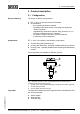
3 Product description
3.1 Configuration . . . . . . . . . . . . . . . . . . . . . . . . . . . . . .
7
3.2 Principle of operation . . . . . . . . . . . . . . . . . . . . . . . .
8
3.3 Operation. . . . . . . . . . . . . . . . . . . . . . . . . . . . . . . . .
8
3.4 Packaging, transport and storage . . . . . . . . . . . . . . .
9
4 Mounting
4.1 General instructions . . . . . . . . . . . . . . . . . . . . . . . . .
10
4.2 Mounting instructions . . . . . . . . . . . . . . . . . . . . . . . .
11
4.3 Mounting steps. . . . . . . . . . . . . . . . . . . . . . . . . . . . .
12
5 Connecting to power supply
5.1 Preparing the connection . . . . . . . . . . . . . . . . . . . . .
13
5.2 Connection procedure. . . . . . . . . . . . . . . . . . . . . . . .
14
5.3 Wiring plan, single chamber housing . . . . . . . . . . . . .
15
5.4 Wiring plan, double chamber housing . . . . . . . . . . . .
16
5.5 Switch on phase. . . . . . . . . . . . . . . . . . . . . . . . . . . .
18
6 Set up with the indicating and adjustment module
6.1 Short description . . . . . . . . . . . . . . . . . . . . . . . . . . .
20
6.2 Insert indicating and adjustment module. . . . . . . . . . .
20
6.3 Adjustment system . . . . . . . . . . . . . . . . . . . . . . . . . .
22
6.4 Setup procedure. . . . . . . . . . . . . . . . . . . . . . . . . . . .
23
6.5 Menu schematic . . . . . . . . . . . . . . . . . . . . . . . . . . . .
32
6.6 Saving the parameter adjustment data . . . . . . . . . . . .
34
7 Setup with PDM
7.1 Parameter adjustment with PDM . . . . . . . . . . . . . . . .
35
8 Maintenance and fault rectification
8.1 Maintenance, cleaning . . . . . . . . . . . . . . . . . . . . . . .
36
8.2 Remove interferences. . . . . . . . . . . . . . . . . . . . . . . .
36
8.3 Instrument repair . . . . . . . . . . . . . . . . . . . . . . . . . . .
38
2 Process pressure transmitter IPT-10 Vers. 2.0 - ceramic sensor • Profibus PA
Contents
31541-EN-081211