Operating Instructions Process pressure transmitter IPT-11 Vers. 4.
Contents Contents 1 About this document 1.1 1.2 1.3 2 . . . . . . . . . . . . . . . . .. .. .. .. .. .. .. .. 5 5 5 5 6 6 6 6 . . . . . . . . . . . . . . . . . . . . . . . . . . . . .. .. .. .. 7 8 8 8 General instructions . . . . . . . . . . . . . . . . . . . . . . . . . Mounting steps. . . . . . . . . . . . . . . . . . . . . . . . . . . . . 10 11 Configuration . . . . . . . . . . . . . . . Principle of operation . . . . . . . . . Operation. . . . . . . . . . . . . . . . . .
Contents 8.2 8.3 9 Remove interferences . . . . . . . . . . . . . . . . . . . . . . . . Instrument repair . . . . . . . . . . . . . . . . . . . . . . . . . . . 39 40 Dismounting 9.1 9.2 Dismounting steps . . . . . . . . . . . . . . . . . . . . . . . . . . Disposal . . . . . . . . . . . . . . . . . . . . . . . . . . . . . . . . . 42 42 10 Supplement 10.1 Technical data . . . . . . . . . . . . . . . . . . . . . . . . . . . . . 10.2 Dimensions . . . . . . . . . . . . . . . . . . . . . . . . . . . . . .
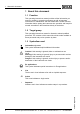
1 About this document 1 About this document 1.1 Function This operating instructions manual provides all the information you need for mounting, connection and setup as well as important instructions for maintenance and fault rectification. Please read this information before putting the instrument into operation and keep this manual accessible in the immediate vicinity of the device. 1.2 Target group This operating instructions manual is directed to trained qualified personnel.
2 For your safety 2 For your safety 2.1 Authorised personnel Mount and set up the pressure transmitter only if you know the applicable national regulations and have the appropriate qualification. You must be aquainted with the regulations and instructions for hazardous areas, measurement and control technology as well as electrical circuits because the pressure transmitter is "electrical equipment" according to EN 50178.
2 For your safety 2.5 Safety approval markings and safety tips The safety approval markings and safety tips on the device must be observed. 2.6 CE conformity This device fulfills the legal requirements of the applicable EC guidelines. By attaching the CE mark, VEGA provides a confirmation of successful testing. 2.7 Fulfillment of NAMUR recommendations With respect to interference resistance and emitted interference, the NAMUR recommendation NE 21 is fulfilled.
3 Product description 3 Product description 3.
3 Product description l l Article number documentation SIL identification (with SIL rating ex works) 3.2 Principle of operation Application area IPT-11 is a pressure transmitter for use in the paper, food processing and pharmaceutical industries as well as in water/sewage water plants. Depending on the version, it is used for level, gauge, absolute pressure or vacuum measurement. Measured products are gases, vapours and liquids, also those containing abrasive substances.
3 Product description The packaging of standard instruments consists of environmentfriendly, recyclable cardboard. For special versions, PE foam or PE foil is also used. Dispose of the packaging material via specialised recycling companies. Transport Transport must be carried out under consideration of the notes on the transport packaging. Nonobservance of these instructions can cause damage to the device.
4 Mounting 4 Mounting 4.1 General instructions Suitability for process conditions Make sure that all parts of the instrument in contact with the measured product, especially the sensor element, process seal and process fitting, are suitable for the existing process conditions such as process pressure, process temperature as well as the chemical properties of the medium. You can find the specifications in chapter "Technical data" in the or on the type label.
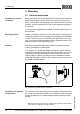
4 Mounting 2 1 Fig. 3: Position of the filter elements 1 2 Filter element for ventilation of the measuring cell Filter element for ventilation of the electronics housing Information: Make sure that the filter elements are always free of buildup during operation. A pressure washer must not be used for cleaning. Temperature limits Higher process temperatures mean often also higher ambient temperatures. 2 1 Fig.
4 Mounting Sealing/Screwing in hygienic fittings Use the seal corresponding to the process fitting. 31546-EN-090130 12 Process pressure transmitter IPT-11 Vers. 4.
5 Connecting to power supply 5 Connecting to power supply 5.1 Preparing the connection Note safety instructions Always keep in mind the following safety instructions: l l Connect only in the complete absence of line voltage If overvoltage surges are expected, overvoltage arresters should be installed Take note of safety instructions for Ex applications In hazardous areas you should take note of the appropriate regulations, conformity and type approval certificates of the sensors and power supply units.
5 Connecting to power supply Select connection cable for Ex applications Take note of the corresponding installation regulations for Ex applications. In particular, make sure that no potential equalisation currents flow over the cable screen. In case of grounding on both sides this can be achieved by the use of a capacitor or a separate potential equalisation. 5.
5 Connecting to power supply 9 Check the hold of the wires in the terminals by lightly pulling on them 10 Connect the screen to the internal ground terminal, connect the outer ground terminal with potential equalisation 11 Tighten the compression nut of the cable entry. The seal ring must completely encircle the cable 12 Screw the housing cover on The electrical connection is finished. 5.3 Wiring plan, single chamber housing The following illustrations apply to the non-Ex as well as to the Ex-ia version.
5 Connecting to power supply Electronics and connection compartment Display I²C 1 4 2 5 6 7 8 1 2 3 Fig. 7: Electronics and connection compartment, single chamber housing 1 2 3 4 Plug connector for service Spring-loaded terminals for connection of the external indicating and adjustment module Ground terminal for connection of the cable screen Spring-loaded terminals for voltage supply Wiring plan Display I2C 1 2 5 6 7 8 1 Fig.
5 Connecting to power supply Housing overview 1 2 3 5 4 Fig. 9: Double chamber housing 1 2 3 4 5 Housing cover, connection compartment Blind stopper or plug M12 x 1 for the external indicating and adjustment module (optional) Housing cover, electronics compartment Filter element for air pressure compensation Cable entry or plug Electronics compartment 1 Display I²C 1 2 5 6 7 8 3 2 Fig.
5 Connecting to power supply Display Connection compartment 1 3 1 I²C 2 2 Fig. 11: Connection compartment, double chamber housing 1 2 3 Plug connector for service Ground terminal for connection of the cable screen Spring-loaded terminals for voltage supply Wiring plan I2C 1 2 1 Fig. 12: Wiring plan, double chamber housing 1 Voltage supply/Signal output 31546-EN-090130 18 Process pressure transmitter IPT-11 Vers. 4.
5 Connecting to power supply 5.5 Wiring plan double chamber housing Ex d Housing overview 1 2 3 5 4 Fig. 13: Double chamber housing 1 2 3 4 5 Housing cover, connection compartment Blind stopper or plug M12 x 1 for the external indicating and adjustment module (optional) Housing cover, electronics compartment Filter element for air pressure compensation Cable entry or plug Electronics compartment 1 Display I²C 1 2 5 6 7 8 3 2 Fig.
5 Connecting to power supply Connection compartment 1 1 2 2 Fig. 15: Connection compartment double chamber housing Ex d 1 2 Spring-loaded terminals for power supply and cable screen Ground terminal for connection of the cable screen Wiring plan 1 2 1 Fig. 16: Wiring plan double chamber housing Ex d 1 Voltage supply/Signal output 5.6 Switch on phase Switch on phase After connecting IPT-11 to power supply or after a voltage recurrence, the instrument carries out a self-check for approx.
5 Connecting to power supply 31546-EN-090130 Then the corresponding current is outputted to the cable (the value corresponds to the actual level as well as the settings already carried out, e.g. factory setting). Process pressure transmitter IPT-11 Vers. 4.
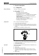
6 Set up with the indicating and adjustment module 6 Set up with the indicating and adjustment module 6.1 Short description Function/Configuration The indicating and adjustment module is used for measured value display, adjustment and diagnosis.
6 Set up with the indicating and adjustment module Fig. 17: Mounting the indicating and adjustment module 31546-EN-090130 Note: If you intend to retrofit the instrument with an indicating and adjustment module for continuous measured value indication, a higher cover with an inspection glass is required. Process pressure transmitter IPT-11 Vers. 4.
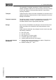
6 Set up with the indicating and adjustment module 6.3 Adjustment system 2 1 1.1 3 Fig.
6 Set up with the indicating and adjustment module 6.4 Setup procedure Address setting HARTMultidrop In HART-Multidrop mode (several sensors on one input) the address must be set before continuing with the parameter adjustment. You will find a detailed description in the operating instructions manual "Indicating and adjustment module" or in the online help of PACTware or DTM.
6 Set up with the indicating and adjustment module To select the adjustment unit (in the example switching over from bar to mbar) you have to proceed as follows:2) 1 ▶ 2 Push the [OK] button in the measured value display, the menu overview is displayed. Basic adjustment Display Diagnostics Service Info Confirm the menu "Basic adjustment" with [OK], the menu item "Unit" will be displayed.
6 Set up with the indicating and adjustment module Unit of measurement Density 0001000 kg/dm³ 6 Enter the requested density value with [->] and [+], confirm with [OK] and move to position correction with [->]. The adjustment unit is hence switched over from bar to m. Proceed as follows to select the temperature unit:3) à Activate the selection with [OK] and select "Temperature unit with [->]. à Activate the selection with [OK] and select the requested unit with [->] (e.g. °F). à Confirm with [OK].
6 Set up with the indicating and adjustment module 5 Confirm with [+] and move to max. adjustment with [->]. The min. adjustment is finished. Information: For an adjustment with filling, you simply enter the displayed actual measured value. If the adjustment ranges are exceeded, the message "Outside parameter limits" appears. The editing procedure can be aborted with [ESC] or the displayed limit value can be accepted with [OK]. Carrying out max.
6 Set up with the indicating and adjustment module The position correction compensates the influence of the mounting position or static pressure on the measurement. It does not influence the adjustment values. In the menu items "zero" and "span" you determine the span of the sensor, the span corresponds to the end value.
6 Set up with the indicating and adjustment module ▶ 2 Basic adjustment Display Diagnostics Service Info Confirm the menu "Basic adjustment" with [OK], the menu item "Unit" will be displayed. Unit Unit of measurement bar▼ Temperature unit °C▼ 3 Activate the selection with [OK] and select "Units of measurement with [->]. 4 Activate the selection with [OK] and select the requested unit with [->] (in the example mbar). 5 Confirm with [OK] and move to position correction with [->].
6 Set up with the indicating and adjustment module Carrying out zero adjustment Proceed as follows: 1 Edit the mbar value in the menu item "zero" with [OK]. Zero adjustment 000.0 % = +0000.0 mbar 0000.0 mbar P 2 Set the requested mbar value with [+] and [->]. 3 Confirm with [+] and move to span adjustment with [->]. The zero adjustment is finished. Information: The zero adjustment shifts the value of the span adjustment. The span, i.e. the difference between these values, however, remains unchanged.
6 Set up with the indicating and adjustment module Copy sensor data This function enables reading out parameter adjustment data as well as writing parameter adjustment data into the sensor via the indicating and adjustment module. A description of the function is available in the operating instructions manual "Indicating and adjustment module".
6 Set up with the indicating and adjustment module Menu section Service Function Reset value Scaling 0.00 to 100.0 Decimal point indication 8888.8 Current output - characteristics 4 … 20 mA Current output - failure < 3.6 mA Current output - min. current 3.8 mA Current output - max. current 20.
6 Set up with the indicating and adjustment module 6.5 Menu schematic Information: Depending on the version and application, the highlighted menu windows are not always available. Basic adjustment ▶ 1 Basic adjustment Display Diagnostics Service Info Unit Unit of measurement bar▼ Temperature unit °C▼ 1.1 Damping 1.5 Position correction Offset = 0.2 mbar 0000 mbar 1.2 Linearisation curve 1.6 P linear ▼ 1s Min. adjustment 000.0 % = 0.0 mbar 0.0 mbar 1.3 Sensor-TAG 1.7 Max. adjustment 100.
6 Set up with the indicating and adjustment module Diagnostics ▶ Basic adjustment Display Diagnostics Service Info Pointer p-min.: -5.8 mbar p-max.: 167.5 mbar T-min.: -12.5 °C T-max.: +85.5 °C 3 3.1 Sensor status 3.2 OK Trend curve 3.3.1 Start trend curve? Service ▶ Basic adjustment Display Diagnostics Service Info Current output 4 4.1 Output mode: 4-20 mA ▼ Fail.mode: < 3.6 mA ▼ Min. current: 3.8 mA ▼ max. current: 20.5 mA ▼ SIL 4.2 Start simulation ▼ 4.
6 Set up with the indicating and adjustment module 6.6 Saving the parameter adjustment data It is recommended noting the adjusted data, e.g. in this operating instructions manual and archive them afterwards. They are hence available for multiple use or service purposes. If IPT-11 is equipped with an indicating and adjustment module, the most important data can be read out of the sensor into indicating and adjustment module.
7 Setup with PACTware and other adjustment programs 7 Setup with PACTware and other adjustment programs 7.1 Connecting the PC Connecting the PC to the signal cable 2 = ~ 3 Power supply HARTModem PACTwareTM / DTM 1 Fig. 19: Connecting the PC to the signal cable 1 2 3 RS232 connection HART resistor 250 Ω IPT-11 3 Necessary components: l l l l l IPT-11 PC with PACTware and suitable WIKA DTM HART modem HART resistor approx.
7 Setup with PACTware and other adjustment programs Note: Keep in mind that for setup of IPT-11, DTM-Collection in the actual version must be used. All currently available WIKA DTMs are provided in the DTM Collection on CD and can be obtained from the responsible WIKA agency for a token fee. This CD includes also the up-to-date PACTware version. The basic version of this DTM Collection incl. PACTware is also available as a free-of-charge download from the Internet. Go via www.wika.com to the item "Service".
8 Maintenance and fault rectification 8 Maintenance and fault rectification 8.1 Maintenance, cleaning When used in the correct way, no special maintenance is required in normal operation. In some applications, product buildup on the sensor diaphragm can influence the measuring result. Depending on the sensor and application, take precautions to ensure that heavy buildup, and especially a hardening thereof, is avoided. If necessary, the transmitter has to be cleaned.
8 Maintenance and fault rectification l No power supply à Check cables for breaks; repair if necessary l Operating voltage too low or load resistance too high à Check, adapt if necessary ? Current signal greater than 22 mA or less than 3.6 mA l electronics module or measuring cell defective à Exchange instrument or return instrument for repair In Ex applications, the regulations for the wiring of intrinsically safe circuits must be observed.
8 Maintenance and fault rectification 31546-EN-090130 By doing this you help us carry out the repair quickly and without having to call back for needed information. Process pressure transmitter IPT-11 Vers. 4.
9 Dismounting 9 Dismounting 9.1 Dismounting steps Warning: Before dismounting, be aware of dangerous process conditions such as e.g. pressure in the vessel, high temperatures, corrosive or toxic products etc. Take note of chapters "Mounting" and "Connecting to power supply" and carry out the listed steps in reverse order. 9.2 Disposal Note: When disposing of old instruments, take note of the valid legal and municipal regulations. The appropriate parts must be recycled.
10 Supplement 10 Supplement 10.1 Technical data General data Parameter, pressure Gauge pressure, absolute pressure, vacuum Measuring principle Ceramic-capacitive, dry measuring cell Service interface I²C bus Materials and weights Material 316L corresponds to 1.4404 or 1.4435 Materials, wetted parts - Process fitting 316L - Diaphragm Ceramic® (99.
10 Supplement Dynamic behaviour output 10 s Run-up time approx. 100 % 90 % 2 1 10 % tT t tA tS Fig.
10 Supplement Adjustment range of the zero/span adjustment relating to the nominal measuring range: - zero -20 … +95 % - span -120 … +120 %8) - Difference between zero and span max. 120 % of the nominal range Recommended max. turn down 10 : 1 (no limitation) Nominal measuring ranges and overload capability in bar/kPa Nominal range Overload, max. pressure Overload, min. pressure Gauge pressure 0 … 0.1 bar/0 … 10 kPa 15 bar/1500 kPa -0.2 bar/-20 kPa 0 … 0.2 bar/0 … 20 kPa 20 bar/2000 kPa -0.
10 Supplement Nominal range Overload, max. pressure Overload, min. pressure Gauge pressure 0 … 1.
10 Supplement Influence of the installation position < 0.2 mbar/20 Pa (0.003 psig) Deviation determined according to the limit point method according to IEC 607709) Applies to digital interfaces (HART, Profibus PA, Foundation Fieldbus) as well as to analogue current output 4 … 20 mA. Specifications refer to the set span. Turn down (TD) is the relation nominal measuring range/set span. Deviation - Turn down 1 : 1 up to 5 : 1 - < 0.075 % Turn down > 5 : 1 < 0.
10 Supplement Process conditions The specifications to the pressure stage and the product temperature are used as an overview. The specifications of the type label are applicable.
10 Supplement Electromechanical data - version IP 66/IP 67 Cable entry/plug13) - Single chamber housing l 1 x cable gland M20 x 1.5 (cable: ø 5 … 9 mm), 1 x blind stopper M20 x 1.5 or: l 1 x closing cap ½ NPT, 1 x blind plug ½ NPT or: - Double chamber housing l 1 x plug (depending on the version), 1 x blind stopper M20 x 1.5 l 1 x cable entry M20 x 1.5 (cable: ø 5 … 9 mm), 1 x blind stopper M20 x 1.
10 Supplement Power supply Operating voltage - Non-Ex instrument 12 … 36 V DC 12 … 30 V DC EEx-ia instrument - Operating voltage with lighted indicating and adjustment module - Non-Ex instrument 20 … 36 V DC 20 … 30 V DC EEx-ia instrument - Permissible residual ripple - < 100 Hz Uss < 1 V 100 Hz … 10 kHz - Uss < 10 mV Load see diagram Ω 1000 750 3 500 2 1 250 4 12 14 16 18 20 22 24 26 28 30 32 34 36 V Fig.
10 Supplement Functional safety (SIL) The functional safety is already activated Ex factory for instruments with SIL qualification. For instruments Ex factory without SIL qualification, the functional safety must be activated by the user for applications according to SIL via the indicating and adjustment module.
10 Supplement 10.2 Dimensions Housing M20x1,5/ ½ NPT ø 77 mm (3 1/32") M20x1,5/ ½ NPT 1 2 M20x1,5/ ½ NPT 3 116mm (4 9/16") ø 84mm (3 5/16") 120mm (4 23/32") ø 77 mm (3 1/32") ~ 116mm (4 9/16") ø 84mm (3 5/16") ~ 87mm (3 27/64") 117 mm (4 39/64") ~ 69 mm (2 23/32") 112 mm (4 13/32") ~ 69 mm (2 23/32") M20x1,5 M20x1,5/ ½ NPT 4 Fig. 22: Housing versions (with integrated indicating and adjustment module the housing is 9 mm/0.
10 Supplement 51mm (2 1/64") 50mm (1 31/32") IPT-11, front-flush connection ø 51mm (2 1/64") SA RT 51mm (2 1/64") 55mm (2 11/64") ø 64mm (2 33/64") ø 66mm (2 19/32") ø 105mm (4 9/64") 3T ø 84mm (3 5/16") 3R 31546-EN-090130 Fig. 23: IPT-11 SA = Tri-Clamp 2", RT = Tri-Clamp 1½", 3T = DRD, 3R = Varivent Form F Process pressure transmitter IPT-11 Vers. 4.
10 Supplement 31546-EN-090130 54 Process pressure transmitter IPT-11 Vers. 4.
31546-EN-090130 10 Supplement Process pressure transmitter IPT-11 Vers. 4.
Printing date:: WIKA Alexander Wiegand GmbH & Co. KG Alexander-Wiegand-Straße 30 63911 Klingenberg/Germany Phone +49 9372 132295 Fax +49 9372 132706 e-mail: support-tronic@wika.de www.wika.de All statements concerning scope of delivery, application, practical use and operating conditions of the sensors and processing systems correspond to the information available at the time of printing.