Operating instructions Betriebsanleitung IUT-10 / IUT-11 Universal transmitter for applications in hazardous environments GB Universaltransmitter für den Einsatz in explosionsgefährdeten Bereichen GB D GB F IUT-10 IUT-11 WIKA Alexander Wiegand GmbH & Co. KG Alexander-Wiegand-Straße 30 63911 Klingenberg/ Germany Tel. (+49) 93 72/132-295 Fax (+49) 93 72/132-706 E-Mail support-tronic@wika.de www.wika.
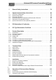
Universal IS Pressure Transmitter UniTrans Contents Contents 2266939.05 D/GB 06/2006 1 General Safety Instructions . . . . . . . . . . . . . . . . . . . . . . . . . . . . . . . . . 79 2 Special Intrinsic Safety Instructions . . . . . . . . . . . . . . . . . . . . . . . . . . 80 2.1 2.2 2.3 2.4 2.5 2.6 Protection of diaphragm . . . . . . . . . . . . . . . . . . . . . . . . . . . . . . . . . . . . . . . . . . . . Special wiring advice . . . . . . . . . . . . . . . . . . . . . . . . . . . . . . . . . .
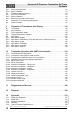
Universal IS Pressure Transmitter UniTrans Contents 8.3.1 8.3.2 8.4 8.4.1 8.4.2 8.4.3 8.5 8.6 Zero Point Calibration . . . . . . . . . . . . . . . . . . . . . . . . . . . . . . . . . . . . . . . . . . . . . . 113 Span Calibration . . . . . . . . . . . . . . . . . . . . . . . . . . . . . . . . . . . . . . . . . . . . . . . . . . 113 Calibration without Pressure. . . . . . . . . . . . . . . . . . . . . . . . . . . . . . . . . . . . . . . . . 114 Zero Point Calibration . . . . . . . . . . . . . . . . . . . .
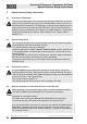
Universal IS Pressure Transmitter UniTrans Contents 1 General Safety Instructions Warning • Select the appropriate pressure transmitter with regard to scale range, performance and specific measurement conditions prior to installing and starting the instrument. • Observe the relevant national regulations (e.g.: EN 50178, NEC, CEC) and observe the applicable standards and directives for special applications (e.g.
Universal IS Pressure Transmitter UniTrans Special Intrinsic Safety Instructions 2 Special Intrinsic Safety Instructions 2.1 Protection of diaphragm Warning 2.
Universal IS Pressure Transmitter UniTrans Special Intrinsic Safety Instructions 2.5 Instructions for temperature ranges Observe the permissible surface temperatures applicable for this range according to the defined temperature classes. Warning Warning Observe the maximum temperature value (of the temperature range defined under item 15.3.4 in the EC type test certificate at the hexagon of the process connection. Protect the pressure transmitter against touching or affix a warning notice.
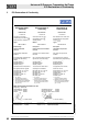
Universal IS Pressure Transmitter UniTrans EC-Declaration of Conformity 3 EC-Declaration of Conformity EG-Konformitätserklärung EC Declaration of Conformity Déclaration de Conformité CE Dokument Nr.: Document No.: Document No.: 11135212.01 11135212.01 11135212.
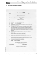
Universal IS Pressure Transmitter UniTrans EC-Type Examination Certificate EC-Type Examination Certificate 2266939.05 D/GB 06/2006 4 Subject to change due to technical modifications. © Copyright WIKA Alexander Wiegand GmbH & Co. KG / Germany WIKA Alexander Wiegand GmbH & Co. KG · Alexander-Wiegand-Str. · 63911 Klingenberg · (09372) 132 - 710 · Fax - 706 · E-mail: support-tronic@wika.de · www.wika.
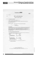
2266939.05 D/GB 06/2006 Universal IS Pressure Transmitter UniTrans EC-Type Examination Certificate 84 Subject to change due to technical modifications. © Copyright WIKA Alexander Wiegand GmbH & Co. KG / Germany WIKA Alexander Wiegand GmbH & Co. KG · Alexander-Wiegand-Str. · 63911 Klingenberg · (09372) 132 - 710 · Fax - 706 · E-mail: support-tronic@wika.de · www.wika.
2266939.05 D/GB 06/2006 Universal IS Pressure Transmitter UniTrans EC-Type Examination Certificate Subject to change due to technical modifications. © Copyright WIKA Alexander Wiegand GmbH & Co. KG / Germany WIKA Alexander Wiegand GmbH & Co. KG · Alexander-Wiegand-Str. · 63911 Klingenberg · (09372) 132 - 710 · Fax - 706 · E-mail: support-tronic@wika.de · www.wika.
2266939.05 D/GB 06/2006 Universal IS Pressure Transmitter UniTrans EC-Type Examination Certificate 86 Subject to change due to technical modifications. © Copyright WIKA Alexander Wiegand GmbH & Co. KG / Germany WIKA Alexander Wiegand GmbH & Co. KG · Alexander-Wiegand-Str. · 63911 Klingenberg · (09372) 132 - 710 · Fax - 706 · E-mail: support-tronic@wika.de · www.wika.
2266939.05 D/GB 06/2006 Universal IS Pressure Transmitter UniTrans EC-Type Examination Certificate Subject to change due to technical modifications. © Copyright WIKA Alexander Wiegand GmbH & Co. KG / Germany WIKA Alexander Wiegand GmbH & Co. KG · Alexander-Wiegand-Str. · 63911 Klingenberg · (09372) 132 - 710 · Fax - 706 · E-mail: support-tronic@wika.de · www.wika.
2266939.05 D/GB 06/2006 Universal IS Pressure Transmitter UniTrans EC-Type Examination Certificate 88 Subject to change due to technical modifications. © Copyright WIKA Alexander Wiegand GmbH & Co. KG / Germany WIKA Alexander Wiegand GmbH & Co. KG · Alexander-Wiegand-Str. · 63911 Klingenberg · (09372) 132 - 710 · Fax - 706 · E-mail: support-tronic@wika.de · www.wika.
2266939.05 D/GB 06/2006 Universal IS Pressure Transmitter UniTrans EC-Type Examination Certificate Subject to change due to technical modifications. © Copyright WIKA Alexander Wiegand GmbH & Co. KG / Germany WIKA Alexander Wiegand GmbH & Co. KG · Alexander-Wiegand-Str. · 63911 Klingenberg · (09372) 132 - 710 · Fax - 706 · E-mail: support-tronic@wika.de · www.wika.
2266939.05 D/GB 06/2006 Universal IS Pressure Transmitter UniTrans EC-Type Examination Certificate 90 Subject to change due to technical modifications. © Copyright WIKA Alexander Wiegand GmbH & Co. KG / Germany WIKA Alexander Wiegand GmbH & Co. KG · Alexander-Wiegand-Str. · 63911 Klingenberg · (09372) 132 - 710 · Fax - 706 · E-mail: support-tronic@wika.de · www.wika.
2266939.05 D/GB 06/2006 Universal IS Pressure Transmitter UniTrans EC-Type Examination Certificate Subject to change due to technical modifications. © Copyright WIKA Alexander Wiegand GmbH & Co. KG / Germany WIKA Alexander Wiegand GmbH & Co. KG · Alexander-Wiegand-Str. · 63911 Klingenberg · (09372) 132 - 710 · Fax - 706 · E-mail: support-tronic@wika.de · www.wika.
2266939.05 D/GB 06/2006 Universal IS Pressure Transmitter UniTrans EC-Type Examination Certificate 92 Subject to change due to technical modifications. © Copyright WIKA Alexander Wiegand GmbH & Co. KG / Germany WIKA Alexander Wiegand GmbH & Co. KG · Alexander-Wiegand-Str. · 63911 Klingenberg · (09372) 132 - 710 · Fax - 706 · E-mail: support-tronic@wika.de · www.wika.
2266939.05 D/GB 06/2006 Universal IS Pressure Transmitter UniTrans EC-Type Examination Certificate Subject to change due to technical modifications. © Copyright WIKA Alexander Wiegand GmbH & Co. KG / Germany WIKA Alexander Wiegand GmbH & Co. KG · Alexander-Wiegand-Str. · 63911 Klingenberg · (09372) 132 - 710 · Fax - 706 · E-mail: support-tronic@wika.de · www.wika.
Universal IS Pressure Transmitter UniTrans EC-Type Examination Certificate Translation by g DMT st 1 Addendum (addition according to Guideline 94/9/EG, appendix III, number 6) to the EC TYPE TEST CERTIFICATE DMT 99 ATEX E 091 U Component: Display model IRU-1*-* Manufacturer: WIKA Alexander Wiegand GmbH & Co. Address: D 63911 Klingenberg / Main Description The display can also be manufactured in compliance with the test documents mentioned in the related test certificate No. BVS PP 99.
2266939.05 D/GB 06/2006 Universal IS Pressure Transmitter UniTrans EC-Type Examination Certificate Subject to change due to technical modifications. © Copyright WIKA Alexander Wiegand GmbH & Co. KG / Germany WIKA Alexander Wiegand GmbH & Co. KG · Alexander-Wiegand-Str. · 63911 Klingenberg · (09372) 132 - 710 · Fax - 706 · E-mail: support-tronic@wika.de · www.wika.
2266939.05 D/GB 06/2006 Universal IS Pressure Transmitter UniTrans EC-Type Examination Certificate 96 Subject to change due to technical modifications. © Copyright WIKA Alexander Wiegand GmbH & Co. KG / Germany WIKA Alexander Wiegand GmbH & Co. KG · Alexander-Wiegand-Str. · 63911 Klingenberg · (09372) 132 - 710 · Fax - 706 · E-mail: support-tronic@wika.de · www.wika.
Universal IS Pressure Transmitter UniTrans Product Description 5 Product Description The intrinsically safe pressure transmitter UniTrans can be used in level control applications as well as for pressure measurement applications in process industry. A variety of process connections, measurement ranges, main boards and display options result in a product for a wide range of applications. 5.
Universal IS Pressure Transmitter UniTrans Product Description 5.1.2 Processing Unit The processing unit, which is integrated in the housing contains the terminal compartment and the keypad used for programming the transmitter. The four keys must be activated (unlocked) before use. During normal operation the keypad is locked to protect data and functions previously entered. The keypad is automatically locked when no key is hit for 10 minutes.
Universal IS Pressure Transmitter UniTrans Product Description Transmitters with displays offer a larger number of programming and processing options. These options include alarm status, damping, signal inversion, tank linearization and diagnostic messages. Display units can be easily upgraded (see chapter 7.2). 5.2 Function The pressure transducer converts the existing pressure into an electrical signal. Microelectronics further process the input signal and produce a proportional 4-20 mA standard signal.
Universal IS Pressure Transmitter UniTrans Product Description 5.2.3 Functional features of transmitters with HART-Communication Universal commands • Displayed unit can be set (mbar, bar, psi, mA, %, m, mm WS ...) (see chapter 10.2.3) • Definition of measuring site description and tag number (see 10.2.3) • Measuring circuit test function (see 10.2.8) • Temperature and min. / max values can be displayed (see chapter 10.2.3) • Nominal pressure range of sensor can be displayed (see chapter 10.2.
Universal IS Pressure Transmitter UniTrans Product Description 5.3 Installation Examples The UniTrans is primarily used to monitor the pressure in pipes, technical equipment and tanks. Depending on the pressure range pressures between 20 mbar up to 4000 bar can be measured. The pressure is measured using absolute (against a vacuum) or relative (against external or air pressure) measurement depending on the type of sensor selected.
Universal IS Pressure Transmitter UniTrans Product Description Level Control: Level Control: Externally mounted Combined pressure and head pressure (with front flat diaphragm) are measured by two externally mounted pressure transducers. The two signals are analyzed and the differential is cal- 2266939.05 D/GB 06/2006 culated by a PLC or suitable signal converter. 102 Subject to change due to technical modifications. © Copyright WIKA Alexander Wiegand GmbH & Co.
Universal IS Pressure Transmitter UniTrans Technical Data 6 Technical Data 6.1 Input-values Pressure Ranges (Absolute pressure upon request) 6.2 / overpressure limit / Burst pressure 0 ... 0.4 bar 2 2.4 0 ... 1,6 bar 10 12 0 ... 6 bar 35 42 0 ... 16 bar 80 96 0 ... 40 bar 80 400 0 ... 100 bar 200 800 0 ... 250 bar 500 1200 0 ... 600 bar 1200 2400 0 ... 1.000 bar 1500 3000 0 ... 1,600 bar 2000 4000 0 ... 2,500 bar 3000 5000 0 ... 4,000 bar 4400 7000 -1 ... +0 bar* 2 2.4 -1 ... +0,6 bar* 10 12 -1 ...
Universal IS Pressure Transmitter UniTrans Technical Data 6.3 Overall deviation (at +10 °C ... +40 °C) better than 0.15 % of span for pressure ranges of < 1000 bar better than 0.6 % for pressure ranges of > 1000 bar Load RA < (UB–12 V)/0.023 A with RA in Ohm and UB in Volt Fault signal 3.6 mA or 21 mA, programmable Integration time 0 s, 1 s, 5 s, 20 s, 40 s, programmable Adjustment of the span Up to Turn Down 1 : 20 Integrated lightning protection optional Zero point adjustment -2.5 ...
Universal IS Pressure Transmitter UniTrans Technical Data Materials Housing Wetted parts (IUT-10) (IUT-11) Wetted parts (IUT-11 EHEDG version) Internal transmission fluid Electrical connection per EN 60 529/ IEC529 highly resistive, fiberglass-enforced plastic (PBT); optionally aluminium CrNi-steel 1.4571 and 2.4711 CrNi-steel 1.4571, o-ring: NBR {Viton or EPDM}; {Hastelloy C4} CrNi-steel 1.4435 Standard {Halocarbon oil for oxygenapplications}; {FDA-approved} M 20 x 1.
Universal IS Pressure Transmitter UniTrans Technical Data 6.6 Storage temperature – 40 °C ... + 85 °C (– 35 °C ... 80 °C with display) Climate class D per DIN IEC 654-1 Ingress protection per EN 60 529 IP 65 for plastic case IP 67 for aluminium case EMC per EN 50 081-2, EN 50 082-2, NAMUR NE 21 Process Conditions °F = (°C * 1.8) + 32 Medium temperatures Attention 6.7 – 30 °C ...
Universal IS Pressure Transmitter UniTrans Technical Data Please pay attention to the information in chapter 7.4. Product labels (example) 2266939.05 D/GB 06/2006 6.8 Subject to change due to technical modifications. © Copyright WIKA Alexander Wiegand GmbH & Co. KG / Germany WIKA Alexander Wiegand GmbH & Co. KG · Alexander-Wiegand-Str. · 63911 Klingenberg · (09372) 132 - 710 · Fax - 706 · E-mail: support-tronic@wika.de · www.wika.
Universal IS Pressure Transmitter UniTrans Installation 7 Installation The device should be installed/operated in accordance with the regulations of ElexV, the Device Safety Regulation, this operating manual and generally recognized industry standards. Before mounting the transmitter make sure to read the operating manual, as well as the EC-type examination certificate. Warning 7.
Universal IS Pressure Transmitter UniTrans Installation Connection Cable Supporting String • All functions are programmable once the pressure transmitter has been upgraded with a display unit. The adjusted parameters are stored after the display unit is removed. The display unit can be rotated in 300°, so that it can be read under various installation conditions. The housing cover with built-in display can be fastened to the housing at all four side positions. 7.
Universal IS Pressure Transmitter UniTrans Installation 7.4 Electrical Connection Warning For the dust approval version, only cable glands and blind plugs with the appropriate ATEX approval may be used. The M12x1 plug may not be used in conjunction with dust approval.(See chapter 2.2) Please observe local installation regulations (Germany: VDE-Standard). The terminal voltage should not exceed 30 V. The transmitter is only to be connected to approved intrinsically safe measuring instruments.
Universal IS Pressure Transmitter UniTrans Installation Terminal Configuration Non-hazardous area Hazardous (classified)area Legend LL+ I Ground Negative Positive Test circuit; connect the ampere meter between terminals L+ and I For transmitters with M12 x 1 circular connector, below are the wiring details: 1 Positive 3 Negative Warning When connecting the clamps ’L+’ and ’I’ the safety-related nominal values (See chapter 6.7) must be observed.
Universal IS Pressure Transmitter UniTrans Operation of Devices without Displays 8 Operation of Devices without Displays 8.1 Preparation This unit can be programmed before or after installation. • Connect an ampere meter to the device’s output (between terminals I and L+). • Note that after each action, a brief oscillation/deflection of 20 mA occurs (verification of a successful action).
Universal IS Pressure Transmitter UniTrans Operation of Devices without Displays 8.3 Calibration with Pressure 8.3.1 Zero Point Calibration Make sure that the pressure to be used as the zero point (P 0 %), is present at the transmitterer diaphragm before calibration. Calibration Value (2 sec.) Confirm Function (2 sec.) (2 sec.) meas Zero point calibration 024-DS-GB 8.3.2 Span Calibration Calibration of the measurement range (span).
Universal IS Pressure Transmitter UniTrans Operation of Devices without Displays 8.4 Calibration without Pressure Determine the current reference values for the zero point and the span to be entered in the transmitter before calibration. This is done as follows: 8.4.1 Zero Point Calibration • Determine the hydrostatic pressure of the liquid’s surface that meets the zero point. • Adjust this pressure in proportion to the sensor’s nominal pressure range.
Universal IS Pressure Transmitter UniTrans Operation of Devices without Displays Example: A pressure transmitter with 0 ... 400 mbar (nominal pressure) is to be programmed. The liquid’s surface (with a density of 1) is 1 m above the diaphragm at the zero point. The maximum (span end-point) should be 3 m. The measuring range (span) is 200 mbar.
Universal IS Pressure Transmitter UniTrans Operation of Devices without Displays 8.4.3 Mounting correction of the sensor The position of the measuring cell is entered by simultaneously pressing (2 sec.) the "zero" and "esc" buttons. Function Calibration Value (2 sec.) (2 sec.) (2 sec.) Mounting correction of the sensor 8.5 049-DS-GB Integration Time (Damping) Adjustment The following integration time settings can be used: 0, 1, 5, 20 and 40 s.
Universal IS Pressure Transmitter UniTrans Operation of Devices without Displays 8.6 Reset to Default All default data settings are restored by simultaneously pressing the "zero", "esc" and the "ok" buttons for 2 seconds (see chapter 9.4) Function Calibration Value (2 sec.) Reset to default (2 sec.) 050-DS-GB Calibrated special measurement ranges i. e. 4 bar on a 6 bar transmitter can be adjusted by factory pre-setting. A reset to default will reset the sensor back to its nominal range (i. e.
Universal IS Pressure Transmitter UniTrans Operation of Transmitters with Display 9 Operation of Transmitters with Display 9.1 The Display 2266939.05 D/GB 06/2006 In order to program the device, remove the display with a screwdriver and re-attach it to the housing as shown in the diagram below. 118 Subject to change due to technical modifications. © Copyright WIKA Alexander Wiegand GmbH & Co. KG / Germany WIKA Alexander Wiegand GmbH & Co. KG · Alexander-Wiegand-Str.
Universal IS Pressure Transmitter UniTrans Operation of Transmitters with Display 9.2 Key Functions Button Functions Main Menu Sub-menu Edit Functions back to the previous menu option back to the previous menu option increase value forward to next menu option forward to next menu option decrease value back to value display without saving back to main menu without saving back without saving to the sub-menu to the edit functions save value activate keypad (push simultaneously; 2 s) 9.
Universal IS Pressure Transmitter UniTrans Operation of Transmitters with Display 9.4 Default Data (factory settings) Function Display Defaults Unit of measurement (Line 1) Line 2 Line 3 Pressure display (in bar) Calibration zero span nom. pressure range start nom. pressure range end Output Damping Inversion Fault Limits I-offset 4 mA 20 mA Service password Temperature display (in °C) Sensor’s nominal pressure range (in bar) 0s no 21 mA (upscale) 3.8 ... 20.
Universal IS Pressure Transmitter UniTrans Operation of Transmitters with Display 9.5 Main Menu DISPLAY OPTIONS see chapter 9.5.1 CALIBRATION RANGE see chapter 9.5.2 OUTPUT DEFINITION see chapter 9.5.3 EVALUATION FUNCTION see chapter 9.5.4 LANGUAGE OPTIONS see chapter 9.5.6 2266939.05 D/GB 06/2006 SERVICE FUNCTIONS see chapter 9.5.5 (not available for transmitters with HARTCommunication option) Subject to change due to technical modifications. © Copyright WIKA Alexander Wiegand GmbH & Co.
Universal IS Pressure Transmitter UniTrans Operation of Transmitters with Display 9.5.1 Main Menu: Display DISPLAY OPTIONS UNIT DISPLAYED UNIT Units are set for the measured value. see *) **)For volume-based units it is necessary to enter the reference value (100% = 0.0, value range 0 ... 3000). *) mbar bar PSI at kg/cm² mA % mm m inch 1.05 feet Pa DISPLAY ROW 2 UNIT mmHG Units are set for the measured value. UNIT l VOL_REF 100% = 0.0 Units are set for the volume-related value.
Universal IS Pressure Transmitter UniTrans Operation of Transmitters with Display DISPLAY ROW 3 ROW 3 MEASURE % ROW 3 BLANK Third line shows measured value in % Third line remains empty ROW 3 MIN VALUE ROW 3 MEASUREMENT ROW 3 TEMPERATURE Third line shows minimum values TEMPERATURE in oC TEMPERATURE in oF ROW 3 MAX VALUE ROW 3 MEASUREMENT ROW 3 TEMPERATURE TEMPERATURE in oC 2266939.05 D/GB 06/2006 Subject to change due to technical modifications.
Universal IS Pressure Transmitter UniTrans Operation of Transmitters with Display 9.5.
Universal IS Pressure Transmitter UniTrans Operation of Transmitters with Display 9.5.3 Main Menu: Output DAMPING Damping 40 s active DAMPING Damping 20 s active DAMPING Damping 5 s active DAMPING MAIN MENU OUTPUT Damping 1 s active OUTPUT OUTPUT DEFINITION DAMPING DAMPING Damping 0 s active OUTPUT OUTPUT INVERSION REVERSION Output is inverted (20 mA ... 4 mA) or not inverted (4 mA ... 20 mA) OUTPUT Alarm at 3.
Universal IS Pressure Transmitter UniTrans Operation of Transmitters with Display 9.5.4 Main Menu: Evaluation The level value and volume value always be adjusted or verified in order to store a value pair. MAIN MENU EVALUATION EVALUATION FUCTIONS EVALUATION REF. TABLE REF.
Universal IS Pressure Transmitter UniTrans Operation of Transmitters with Display Example: Please check the following if "Wrong Entry" appears in the Evaluation menu: • whether or not more than 32 value pairs are entered in the table for tank linearization (please note: P 0 and P 31 are fixed at 0% and 100% respectively) • whether or not an existing height value was tried to be stored again Please enter correct values. Level 100 %: 4000 mm Density: 1 g/cm3 Density correction: 0.
Universal IS Pressure Transmitter UniTrans Operation of Transmitters with Display 9.5.5 Main Menu: Language 2266939.05 D/GB 06/2006 The displayed language for transmitters with HART-Communication is always English. No other language can be selected. 128 Subject to change due to technical modifications. © Copyright WIKA Alexander Wiegand GmbH & Co. KG / Germany WIKA Alexander Wiegand GmbH & Co. KG · Alexander-Wiegand-Str.
Universal IS Pressure Transmitter UniTrans Operation of Transmitters with Display 9.5.6 Main Menu: Service MAIN MENU SERVICE SERVICE FUNCTIONS MOUNTING CORRECTION SERVICE LOOPTEST Mounting correction is performed; sensor must be correctly positioned / mounted and without pressure. CIRCUIT TEST The set current value is used as the test signal until the "esc" button is pressed SERVICE DEVICE DATA SERVICE TIMER Hrs.-TOTAL Total number of operating hours. Hrs.
Universal IS Pressure Transmitter UniTrans Transmitter Operation with HART®-functionality 10 Transmitter Operation with HART®-functionality 10.1 Possible HART® connections Transmitters with HART®-functionality can be operated via a HART®-hand terminal (HC 275), via PC with PactWare and HART®-Modem, or with a remote-I/O-system with HART®-ability (e.g. Pepperl+Fuchs HART®-Multiplexer or Pepperl+Fuchs RPISystem). 10.1.
Universal IS Pressure Transmitter UniTrans Transmitter Operation with HART®-functionality 10.1.2 Connecting the HART®-modem for PC operation The HART®-modem connects the pressure transmitter with HART®-functionality with the serial RS 232 C interface of a PC. In this constellation the parameters of the pressure transmitter can be set via the software PACTware. A respective HART® modem can be ordered from WIKA. Hazardous (Classified) area Non-hazardous area IUT-10 / IUT-11 4 mA ...
Universal IS Pressure Transmitter UniTrans Transmitter Operation with HART®-functionality If the resistances of the devices connected to the power supply/signal line (voltage source) are less than 250 Ω, a minimum resistance of 250 Ω must be installed in the power supply line. The sum of the internal capacitances and inductances of the components used must not exceed the highest permissible values of the ia IIC circuit. Non-hazardous area IUT-10 / IUT-11 4 mA ...
Universal IS Pressure Transmitter UniTrans Transmitter Operation with HART®-functionality 10.2.1 Menu 'Device info' The screen 'Device info' displays all important information of the transmitter, which cannot be modified. 2266939.05 D/GB 06/2006 10.2.2 Menu 'Description' In the fields of the menu 'Description' the name and description of the selected instrument are given. The texts can be edited and saved in a file, but not in the transmitter. Subject to change due to technical modifications.
Universal IS Pressure Transmitter UniTrans Transmitter Operation with HART®-functionality 10.2.3 Submenu 'Parameter' - Device info Polling address: Address of the UniTrans in "short integer" format. Change in dev.: Modify polling address in the transmitter When this message pops up you should consider the described consequences and then decide whether to change the address or stay with the actual address. Long address: 38-bit-address as worldwide device-unique identifier Tag: Desc.
Universal IS Pressure Transmitter UniTrans Transmitter Operation with HART®-functionality Last parametrization: Date of last parametrization Unit of measured value: Units of measured value: • mbar, bar PSI, atm, mA, %, mm, m, inch, feet, Pa, kPa, Mpa, mmWS, mmHG Volume-related units: • l, kg, t, m3, gal, lb When height is displayed or calibrated (e. g. mm, m, feet, inch) the density value of the respective medium must be entered in order to calculate the correct filling level (see also chapter 10.2.6).
Universal IS Pressure Transmitter UniTrans Transmitter Operation with HART®-functionality 10.2.4 Submenu 'Parameter' - Calibration Calibration with pressure: The calibration with pressure is only possible when the cyclic measurement is activated. Set zero: Before starting the calibration make sure that the pressure applied to the transmitter has the value you want to set as zero point (P 0 %).
Universal IS Pressure Transmitter UniTrans Transmitter Operation with HART®-functionality Calibration without pressure: Zero: • Here a pressure value within the nominal pressure range of the transmitter must be entered. Span: • Here a pressure value for the span within the nominal pressure range of the transmitter must be entered. When calibrating without pressure (dry calibration), a sensor mounting correction should be carried out before or after the calibration (see also chapter 10.2.7 ).
Universal IS Pressure Transmitter UniTrans Transmitter Operation with HART®-functionality 10.2.5 Submenu 'Parameter' - Output Damping: An average value of the pressure values applied to the sensor is calculated over the predefined integration time. The following integration times can be set: • 0, 1, 5, 20 and 40 s. Output inversion: The output signal can be inverted or not inverted. • inverted 20 ... 4 mA • not inverted 4 ...
Universal IS Pressure Transmitter UniTrans Transmitter Operation with HART®-functionality 10.2.6 Submenu 'Parameter' - Evaluation Evaluation: Here the relation between height values and volume values is given in a graph. Function: • Linear: Here a linear relation between height and volume values is set. • Table: The values of the table are set as linearisation graph between height and volume value. 2266939.
Universal IS Pressure Transmitter UniTrans Transmitter Operation with HART®-functionality Check lin. table: The entered linearization table is subject to a plausibility check. If wrong or incomplete values are entered the following error window pops up. Media density: Here the density of the medium is given in g/cm³ 2266939.
Universal IS Pressure Transmitter UniTrans Transmitter Operation with HART®-functionality 10.2.7 Window 'Service' You can open the 'Service' window under 'Device' via the 'Service' menu item or in the 'Context' menu (right mouse button) for the device that is selected in the navigation window (project view). The following warning will pop up while you browse to the window 'Service'.
Universal IS Pressure Transmitter UniTrans Transmitter Operation with HART®-functionality Timer: • Hrs-TOTAL: display of overall operating hours • Hrs-CALIB: display of operating hours since last calibration • Hrs-RESET: display of operating hours since last reset • Hrs-SENSOR: display of sensor operating hours Reset: Via the four buttons certain functions of the transmitter are reset. • Timer: Reset of operating hours • Alarm 4 - 20 mA: Alarm reset when the 4 ...
Universal IS Pressure Transmitter UniTrans Transmitter Operation with HART®-functionality 10.2.8 Window 'Simulation' You can open the 'Simulation' window under 'Device' via the 'Simulation' menu item or in the 'Context' menu (right mouse button) for the device that is selected in the navigation window (project view). The following warning will pop up while you browse to the window 'Simulation'.
Universal IS Pressure Transmitter UniTrans Transmitter Operation with HART®-functionality 10.2.9 Window 'Measured value' You can open the 'measured value' window under 'Device' - 'Display' in the 'Measured value' menu item or in the 'Context' menu (right mouse button) for the instrument that has been selected in the navigation window (project view).
Universal IS Pressure Transmitter UniTrans Transmitter Operation with HART®-functionality 10.2.11 Window 'Burst mode' You can open the 'Burst mode' window in the 'Context' menu (right mouse button) for the device that is selected in the navigation window (project view). In the burst mode UniTrans sends actual values to the master on a cyclic basis. • Current • %-value and current • Pressure, temperature and current If Burst mode is active a parametrization is not possible. 10.2.
Universal IS Pressure Transmitter UniTrans Diagnostics and Service 11 Diagnostics and Service Attention If a failure cannot be repaired, the transmitter must be switched off.The operator then must make sure that it is only switched on again after the failure has been repaired. Repairs should only be carried out by the manufacturer. All other repairs or modifications are unauthorized. The following error messages can appear on devices with displays (see chapter 5.1.
Universal IS Pressure Transmitter UniTrans Appendix Appendix 13.1 Dimension Diagrams 2266939.05 D/GB 06/2006 13 Subject to change due to technical modifications. © Copyright WIKA Alexander Wiegand GmbH & Co. KG / Germany WIKA Alexander Wiegand GmbH & Co. KG · Alexander-Wiegand-Str. · 63911 Klingenberg · (09372) 132 - 710 · Fax - 706 · E-mail: support-tronic@wika.de · www.wika.
2266939.05 D/GB 06/2006 Universal IS Pressure Transmitter UniTrans Appendix 148 Subject to change due to technical modifications. © Copyright WIKA Alexander Wiegand GmbH & Co. KG / Germany WIKA Alexander Wiegand GmbH & Co. KG · Alexander-Wiegand-Str. · 63911 Klingenberg · (09372) 132 - 710 · Fax - 706 · E-mail: support-tronic@wika.de · www.wika.
2266939.05 D/GB 06/2006 Universal IS Pressure Transmitter UniTrans Appendix Subject to change due to technical modifications. © Copyright WIKA Alexander Wiegand GmbH & Co. KG / Germany WIKA Alexander Wiegand GmbH & Co. KG · Alexander-Wiegand-Str. · 63911 Klingenberg · (09372) 132 - 710 · Fax - 706 · E-mail: support-tronic@wika.de · www.wika.
2266939.05 D/GB 06/2006 Universal IS Pressure Transmitter UniTrans Appendix 150 Subject to change due to technical modifications. © Copyright WIKA Alexander Wiegand GmbH & Co. KG / Germany WIKA Alexander Wiegand GmbH & Co. KG · Alexander-Wiegand-Str. · 63911 Klingenberg · (09372) 132 - 710 · Fax - 706 · E-mail: support-tronic@wika.de · www.wika.
Universal IS Pressure Transmitter UniTrans Appendix 13.2 Model Key Signal output 4 ... 20 mA, 2-wire A 1 2 3 4 ... 20 mA with HART® protocol, 2-wire 1) Unit B bar S bar absolut Pressure range CA -1 bar ... 0 bar CD -1 bar ... 0,6 bar BM 0 bar ... 40 bar BO 0 bar ... 100 bar CH -1 bar ... 3 bar CK -1 bar ... 5 bar BQ 0 bar ... 250 bar BT 0 bar ... 600 bar CP -1 bar ... 15 bar BU 0 bar ... 1000 bar R BB 0 bar ... 0.4 bar / bar absolute BV 0 bar ... 1600 bar2 BE 0 bar ... 1.
Universal IS Pressure Transmitter UniTrans Appendix 1 A R 2 B S 3 CA CD CH CK CP BB BE 4 85 86 G6 83 5 1 L B S 6 Z E O 7 M A 8 M A Z 9 A L X 4 ... 20 mA with HART® protocol, 2-wire 1) Unit bar bar absolut Pressure range -1 bar ... 0 bar -1 bar ... 0,6 bar -1 bar ... 3 bar -1 bar ... 5 bar -1 bar ... 15 bar 0 bar ... 0,4 bar / bar absolute 0 bar ...
Universal IS Pressure Transmitter UniTrans Appendix 13.3 Warranty Conditions The pressure transmitter has a 24 month warranty in accordance with the WIKA General Terms of Delivery. Repairs may only be carried out by the manufacturer. All other repairs and device modifications are unauthorized and will void the warranty. Warning 13.4 Glossary Adjustment Allocation of the signal output range (4 ... 20 mA) to the desired pressure measurement range or level measurement range.