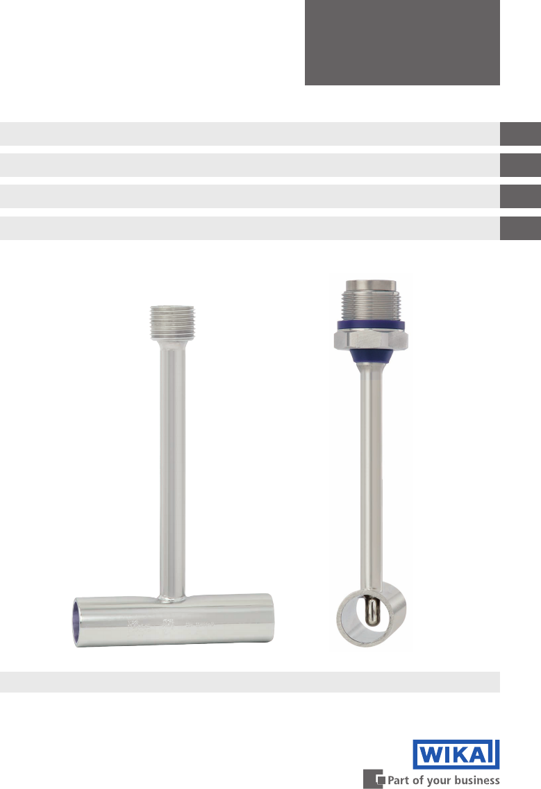
Operating instructions Betriebsanleitung Mode d'emploi Manual de instrucciones Thermowell for sanitary applications, model TW61 GB Schutzrohr für die sterile Verfahrenstechnik, Typ TW61 D Doigt de gant pour applications sanitaires, type TW61 F Vaina para procesos estériles, modelo TW61 E Thermowells model TW61
GB Operating instructions model TW61 Page 3 - 18 D Betriebsanleitung Typ TW61 Seite 19 - 34 F Mode d'emploi type TW61 Page 35 - 50 E Manual de instrucciones modelo TW61 Página 51 - 65 © 2012 WIKA Alexander Wiegand SE & Co. KG All rights reserved. / Alle Rechte vorbehalten. WIKA® is a registered trademark in various countries. WIKA® ist eine geschützte Marke in verschiedenen Ländern.
Contents Contents GB 1. General information 4 3. Specifications 7 2. Safety 4. Design and function 5 7 5. Transport, packaging and storage 12 7. Maintenance and cleaning 13 6. Commissioning, operation 8. Faults 9. Dismounting, return and disposal Appendix 1: TÜV certificate Appendix 2: EC declaration of conformity 12 14 15 16 18 11593963.03 03/2014 GB/D/F/E Declarations of conformity can be found online at www.wika.com.
1. General information 1. General information ■■ The thermowells described in these operating instructions have been designed and manufactured using state-of-the-art technology. All components are subject to stringent quality and environmental criteria during production. Our management systems are certified to ISO 9001 and ISO 14001. GB ■■ These operating instructions contain important information on handling the thermowell.
1. General information / 2. Safety DANGER! ... identifies hazards due to electrical power. Should the safety instructions not be observed, there is a risk of serious or fatal injury. GB WARNING! ... indicates a potentially dangerous situation that can result in burns, caused by hot surfaces or liquids, if not avoided. 2. Safety WARNING! Before installation, commissioning and operation, ensure that the appropriate thermowell has been selected in terms of design and specific measuring conditions.
2. Safety 2.2 Personnel qualification WARNING! Risk of injury should qualification be insufficient! Improper handling can result in considerable injury and damage to equipment. ■■ The activities described in these operating instructions may only be carried out by skilled personnel who have the qualifications described below. ■■ Keep unqualified personnel away from hazardous areas.
3. Specifications / 4. Design and function 3. Specifications Specifications Designs of connection Nominal width of tube Permissible temperature ranges Model TW61 Flow-through housing or angular housing Pipe classes per DIN, ISO and ASME BPE see table of dimensions, chapter 4.2 “Dimensions and pressure ratings” ■■ Ambient ■■ Medium to be measured -40 ... +85 °C -50 ... +250 °C ■■ Pipes to DIN 11866 series A (metric) and Stainless steel 1.
4. Design and function 4.2 Dimensions in mm ■■ Flow-through housing 11610565.01 For model TR21-B miniature resistance thermometer 1) Output signal Pt100 Output signal 4 ... 20 mA 1) In the event of replacement, calculate sensor length, A, as follows: ATR21-B = U1 + M + 3 mm pre-load 1) In the event of replacement, select a resistance thermometer measuring insert model TR22-B.
4. Design and function Metric or DIN 11866 series A Nominal width of tube OD 10 15 20 25 32 40 50 65 80 100 Nominal pressure in bar PN 1) 2) 25 25 25 25 25 25 25 16 16 12.5 Outer diameter of pipe ØD 13 19 23 29 35 41 53 70 85 104 Tube length s TL U1 M Tube wall thickness Tube length Thermowell insertion length TR21-B TR22-B 51 48 46 46 39 39 39 27 27 12 1.5 1.5 1.5 1.5 1.5 1.5 1.5 2.0 2.0 2.
4. Design and function ■■ Angular housing (recommended mounting position, see chapter 6 “Commissioning, operation”) 11610565.01 For model TR21-B miniature resistance thermometer GB Output signal 4 ... 20 mA 1) 1) In the event of replacement, calculate sensor length, A, as follows: ATR21-B = U1 + M + 3 mm Output signal Pt100 1) In the event of replacement, select a resistance thermometer measuring insert model TR22-B.
4. Design and function Metric or DIN 11866 series A Nominal width of tube OD 10 15 20 25 32 40 50 65 80 100 Nominal pressure in bar Outer Tube wall diameter thickness of pipe Tube length 25 25 25 25 25 25 25 16 16 12.5 13 19 23 29 35 41 53 70 85 104 35 35 40 50 55 60 80 105 130 155 PN 1) 2) ØD s 1.5 1.5 1.5 1.5 1.5 1.5 1.5 2.0 2.0 2.0 ISO tubes or DIN 11866 series B Nominal width of tube OD 13.5 17.2 21.3 26.9 33.7 42.4 48.3 60.3 76.1 88.
5. Transport, packaging and storage / 6. Commissioning, ... 5. Transport, packaging and storage 5.1 Transport Check the thermowell for any damage that may have been caused by transport. GB Obvious damage must be reported immediately. 5.2 Packaging Do not remove packaging until just before mounting. Keep the packaging as it will provide optimum protection during transport (e.g. change in installation site, sending for repair). 5.
6. Commissioning, operation / 7. Maintenance and cleaning Recommended installation for the angular housing design Concerning the angular housing design it is recommended, to install the sensor horizontally and not vertically in the pipeline. Consequently the formation of an air pocket during sterilization in the cupola is avoided. 7. Maintenance and cleaning 7.1 Maintenance In general, thermowells are maintenance-free.
8. Faults / 9. Dismounting, return and disposal 8. Faults Faults Measures Remove foreign bodies Clean the threads Return the thermowell (see chapter 9.
9. Dismounting, return and disposal 9.2 Return WARNING! Absolutely observe the following when shipping the instrument: All instruments delivered to WIKA must be free from any kind of hazardous substances (acids, leachate, solutions, etc.). GB When returning the instrument, use the original packaging or a suitable transport package. To avoid damage: 1. Wrap the instrument in an antistatic plastic film. 2. Place the instrument, along with shock-absorbent material, in the packaging.
Appendix 1: TÜV certificate 11593963.
Appendix 2: EC declaration of conformity 11593963.
11593963.
Inhalt Inhalt 1. Allgemeines 20 3. Technische Daten 23 2. Sicherheit 4. Aufbau und Funktion 5. Transport, Verpackung und Lagerung 6. Inbetriebnahme, Betrieb 7. Wartung und Reinigung 8. Störungen 9. Demontage, Rücksendung und Entsorgung Anlage 1: TÜV-Zertifikat Anlage 2: EG-Konformitätserklärung 21 23 28 28 29 30 30 32 34 11593963.03 03/2014 GB/D/F/E Konformitätserklärungen finden Sie online unter www.wika.de.
1. Allgemeines 1. Allgemeines ■■ Die in der Betriebsanleitung beschriebenen Schutzrohre werden nach dem aktuellen Stand ■■ Diese Betriebsanleitung gibt wichtige Hinweise zum Umgang mit dem Schutzrohr. Voraussetzung für sicheres Arbeiten ist die Einhaltung aller angegebenen Sicherheitshinweise und Handlungsanweisungen. ■■ Die für den Einsatzbereich des Schutzrohres geltenden örtlichen Unfallverhütungsvorschriften und allgemeinen Sicherheitsbestimmungen einhalten.
1. Allgemeines / 2. Sicherheit GEFAHR! … kennzeichnet Gefährdungen durch elektrischen Strom. Bei Nichtbeachtung der Sicherheitshinweise besteht die Gefahr schwerer oder tödlicher Verletzungen. WARNUNG! … weist auf eine möglicherweise gefährliche Situation hin, die durch heiße Oberflächen oder Flüssigkeiten zu Verbrennungen führen kann, wenn sie nicht gemieden wird. D 2.
2. Sicherheit 2.2 Personalqualifikation WARNUNG! Verletzungsgefahr bei unzureichender Qualifikation! Unsachgemäßer Umgang kann zu erheblichen Personen- und Sachschäden führen. ■■ Die in dieser Betriebsanleitung beschriebenen Tätigkeiten nur durch Fachpersonal nachfolgend beschriebener Qualifikation durchführen lassen. ■■ Unqualifiziertes Personal von den Gefahrenbereichen fernhalten.
3. Technische Daten / 4. Aufbau und Funktion 3. Technische Daten Technische Daten Bauformen Rohr-Nennweite Zulässige Temperaturbereiche ■■ Umgebung ■■ Messmedium Werkstoffe (messstofberührte Bauteile) ■■ Rohre nach DIN 11866 Reihe A (metrisch) und Reihe B (ISO) ■■ Rohre nach DIN 11866 Reihe C (ASME BPE) Anschluss zum Thermometer Typ TW61 Durchgangsgehäuse oder Eckgehäuse Rohrklassen nach DIN, ISO und ASME BPE siehe Maßtabellen Kapitel 4.2 „Abmessungen und Druckstufen“ -40 ... +85 °C -50 ...
4. Aufbau und Funktion 4.2 Abmessungen in mm ■■ Durchgangsgehäuse 11610565.01 Für Miniatur-Widerstandsthermometer Typ TR21-B D 1) Ausgangssignal Pt100 Ausgangssignal 4 ... 20 mA 1) Im Ersatzfall errechnet sich die Sensorlänge A wie folgt: ATR21-B = U1 + M + 3 mm 11593963.03 03/2014 GB/D/F/E 1) 11528266.01 Vorspannung 1) Im Ersatzfall ist ein Widerstandsthermometer-Messeinsatz Typ TR22-B zu wählen.
4. Aufbau und Funktion Metrisch bzw. DIN 11866 Reihe A RohrNenndruck RohrNennweite in bar außen-Ø OD 10 15 20 25 32 40 50 65 80 100 PN 1) 2) 25 25 25 25 25 25 25 16 16 12,5 ØD 13 19 23 29 35 41 53 70 85 104 ISO-Rohre bzw. DIN 11866 Reihe B RohrNenndruck RohrNennweite in bar außen-Ø OD 13,5 17,2 21,3 26,9 33,7 42,4 48,3 60,3 76,1 88,9 PN 1) 2) 25 25 25 25 25 25 25 25 16 16 ØD 13,5 17,2 21,3 26,9 33,7 42,4 48,3 60,3 76,1 88,9 ASME BPE bzw.
4. Aufbau und Funktion ■■ Eckgehäuse (empfohlene Einbaulage, siehe Kapitel 6 „Inbetriebnahme, Betrieb“) 11610565.01 Für Miniatur-Widerstandsthermometer Typ TR21-B D Ausgangssignal 4 ... 20 mA 1) 1) Im Ersatzfall errechnet sich die Sensorlänge A wie folgt: ATR21-B = U1 + M + 3 mm Ausgangssignal Pt100 1) Im Ersatzfall ist ein WiderstandsthermometerMesseinsatz Typ TR22-B zu wählen.
4. Aufbau und Funktion Metrisch bzw.
5. Transport, Verpackung, Lagerung / 6. Inbetriebnahme, ... 5. Transport, Verpackung und Lagerung 5.1 Transport Das Schutzrohr auf eventuell vorhandene Transportschäden untersuchen. Offensichtliche Schäden unverzüglich mitteilen. D 5.2 Verpackung Verpackung erst unmittelbar vor der Montage entfernen. Die Verpackung aufbewahren, denn diese bietet bei einem Transport einen optimalen Schutz (z. B. wechselnder Einbauort, Reparatursendung). 5.
6. Inbetriebnahme, Betrieb / 7. Wartung und Reinigung Einbauempfehlung für die Ausführung mit Eckgehäuse Bei der Ausführung mit Eckgehäuse wird empfohlen, den Fühler waagerecht und nicht senkrecht in die Rohrleitung einzubauen. Somit wird die Bildung eines Luftpolsters während der Sterilisation im Dom vermieden. D 7. Wartung und Reinigung 7.1 Wartung Schutzrohre sind im Allgemeinen wartungsfrei.
8. Störungen / 9. Demontage, Rücksendung und Entsorgung 8. Störungen Störungen Ursachen Maßnahmen Fremdkörper im Schutzrohr Fremdkörper entfernen Verschmutzte Befestigungsgewinde von Schutzrohr oder Temperaturfühler Beschädigte Befestigungsgewinde von Schutzrohr oder Temperaturfühler Schutzrohr oder Fühler wurde bei Montage verbogen oder beschädigt Austritt von Prozess- Bei Austritt von Prozessmedium am medium Prozessanschluss können Fehler bei der Montage oder fehlerhafte Dichtungen die Ursache sein.
9. Demontage, Rücksendung und Entsorgung 9.2 Rücksendung WARNUNG! Beim Versand des Gerätes unbedingt beachten: Alle an WIKA gelieferten Geräte müssen frei von Gefahrstoffen (Säuren, Laugen, Lösungen, etc.) sein. Zur Rücksendung des Gerätes die Originalverpackung oder eine geeignete Transportverpackung verwenden. Um Schäden zu vermeiden: 1. Das Gerät in eine antistatische Plastikfolie einhüllen. 2. Das Gerät mit dem Dämmmaterial in der Verpackung platzieren.
Anlage 1: TÜV-Zertifikat 11593963.
Anlage 2: EG-Konformitätserklärung 11593963.
11593963.
Sommaire Sommaire 1. Généralités 2. Sécurité 3. Spécifications 4. Conception et fonction 5. Transport, emballage et stockage 6. Mise en service, exploitation 7. Entretien et nettoyage 8. Dysfonctionnements 9. Démontage, retour et mise au rebut Annexe 1 : Certificat du TÜV (contrôle technique allemand) Annexe 2 : Déclaration de conformité CE 36 37 39 39 44 44 45 46 46 48 49 11593963.03 03/2014 GB/D/F/E Déclarations de conformité se trouve sur www.wika.fr.
1. Généralités 1. Généralités ■■ Les doigts de gant décrits dans ce mode d'emploi sont conçus et fabriqués selon les dernières technologies en vigueur. Tous les composants sont soumis à des critères de qualité et d'environnement stricts durant la fabrication. Nos systèmes de gestion sont certifiés selon ISO 9001 et ISO 14001. ■■ Ce mode d'emploi donne des indications importantes concernant l'utilisation du doigt de gant.
1. Généralités / 2. Sécurité DANGER ! … indique les dangers liés au courant électrique. Danger de blessures graves ou mortelles en cas de non respect des consignes de sécurité. AVERTISSEMENT ! … indique une situation présentant des risques susceptibles de provoquer des brûlures dues à des surfaces ou liquides chauds si elle n'est pas évitée. F 2.
2. Sécurité 2.2 Qualification du personnel Personnel qualifié Le personnel qualifié est, en raison de sa formation spécialisée, de ses connaissances dans le domaine de la technique de mesure et de régulation et de ses expériences de même que de sa connaissance des prescriptions nationales, des normes et directives en vigueur, en mesure d'effectuer les travaux décrits et de reconnaître automatiquement les dangers potentiels.
3. Spécifications / 4. Conception et fonction 3. Spécifications Spécifications Formes du raccord Taille nominale du tube Plages de température admissibles ■■ Ambiante ■■ Fluide à mesurer Matériaux (parties en contact avec le fluide) ■■ Tuyauteries pour DIN 11866 série A (métrique) et série B (ISO) ■■ Tuyauteries pour DIN 11866 série C (ASME BPE) Raccord au thermomètre Type TW61 Montage en ligne ou montage coudé Classes de tube selon DIN, ISO et ASME BPE voir tableau des dimensions, chapitre 4.
4. Conception et fonction 4.2 Dimensions en mm ■■ Montage en ligne 11610565.01 Pour sonde à résistance miniature type TR21-B F 1) Signal de sortie Pt100 Signal de sortie 4 ... 20 mA 1) En cas de remplacement, calculer la longueur du capteur, A, comme suit : ATR21-B = U1 + M + 3 mm 14006093.02 11593963.03 03/2014 GB/D/F/E 1) 11528266.01 1) Dans le cas d’un remplacement, choisir un insert de mesure pour la sonde à résistance de type TR22-B.
4.
4. Conception et fonction ■■ Montage angulaire (position de montage recommandée, voir chapitre 6 “Mise en service, exploitation”) 11610565.01 Pour sonde à résistance miniature type TR21-B F Signal de sortie 4 ... 20 mA 1) 1) En cas de remplacement, calculer la longueur du capteur, A, comme suit : ATR21-B = U1 + M + 3 mm Signal de sortie Pt100 1) Dans le cas d’un remplacement, choisir un insert de mesure pour la sonde à résistance de type TR22-B.
4.
5. Transport, emballage et stockage / 6. Mise en service, ... 5. Transport, emballage et stockage 5.1 Transport Vérifier s'il existe des dégâts sur le doigt de gant liés au transport. Communiquer immédiatement les dégâts constatés. 5.3 Stockage Conditions admissibles sur le lieu de stockage : ■■ Température de stockage : 0 ... 70 °C ■■ Humidité : 35 ...
6. Mise en service, exploitation / 7. Entretien et nettoyage Installation recommandée pour la version pour montage angulaire Concernant la version pour montage angulaire, il est recommandé d'installer le capteur à l'horizontale et non verticalement dans la tuyauterie. De cette façon, on évite la formation d'une poche d'air dans la coupole pendant la stérilisation. F 7. Entretien et nettoyage 7.1 Entretien En général, les doigts de gant ne nécessitent aucune maintenance.
8. Dysfonctionnements / 9. Démontage, retour, mise au rebut 8.
9. Démontage, retour et mise au rebut 9.2 Retour AVERTISSEMENT ! Il faut absolument observer les consignes suivantes lors de l'expédition de l'instrument : Tous les instruments envoyés à WIKA doivent être exempts de toute substance dangereuse (acides, lixiviats, solutions, etc.). Pour retourner l'instrument, utiliser l'emballage original ou un emballage adapté pour le transport. Pour éviter des dommages : 1. Emballer l'instrument dans une feuille de plastique antistatique. 2.
Annexe 1 : Certificat du TÜV (contrôle technique allemand) 11593963.
Annexe 2 : Déclaration de conformité CE 11593963.
11593963.
Contenido Contenido 1. Información general 52 3. Datos técnicos 55 2. Seguridad 4. Diseño y función 5. Transporte, embalaje y almacenamiento 6. Puesta en servicio, funcionamiento 7. Mantenimiento y limpieza 8. Fallos 9. Desmontaje, devolución y eliminación Anexo 1: Certificado TÜV (Inspección Técnica) Anexo 2: Declaración de conformidad CE 53 55 60 60 61 62 62 64 65 11593963.03 03/2014 GB/D/F/E Declaraciones de conformidad puede encontrar en www.wika.es.
1. Información general 1. Información general ■■ Las vainas descritas en el manual de instrucciones están fabricadas según el estado actual de la técnica. Todos los componentes están sujetos a rigurosos criterios de calidad y medio ambiente durante la producción. Nuestros sistemas de gestión están certificados según ISO 9001 e ISO 14001. ■■ Este manual de instrucciones proporciona indicaciones importantes acerca del manejo de la vaina.
1. Información general / 2. Seguridad ¡PELIGRO! ... indica riesgos causados por corriente eléctrica. Existe riesgo de lesiones graves o mortales si no se observan estas indicaciones de seguridad. ¡ADVERTENCIA! ... indica una situación probablemente peligrosa que pueda causar quemaduras debido a superficies o líquidos calientes si no se evita. 2.
2. Seguridad 2.2 Cualificación del personal ¡ADVERTENCIA! ¡Riesgo de lesiones debido a una insuficiente cualificación! Un manejo no adecuado puede causar considerables daños personales y materiales. ■■ Las actividades descritas en este manual de instrucciones deben realizarse únicamente por personal especializado con la consiguiente cualificación. ■■ Mantener alejado a personal no cualificado de las zonas peligrosas. Algunas condiciones de uso específicas requieren conocimientos adicionales, p. ej.
3. Datos técnicos / 4. Diseño y función 3. Datos técnicos Datos técnicos Diseño Ancho nominal del tubo Rangos de temperatura admisibles Modelo TW61 Caja de paso o caja angular Clases de tubo según DIN, ISO y ASME BPE véase la tabla de medidas en el capítulo 4.2 “Dimensiones y niveles de presión” ■■ Ambiente ■■ Medio medido -40 ... +85 °C -50 ...
4. Diseño y función 4.2 Dimensiones en mm ■■ Caja de paso 11610565.01 Para termorresistencia miniatura modelo TR21-B E 1) Señal de salida Pt100 Señal de salida 4 ... 20 mA 1) En caso de sustitución, la longitud del sensor A se calcula como sigue: ATR21-B = U1 + M + 3 mm 14006093.02 11593963.03 03/2014 GB/D/F/E 1) 11528266.01 1) En caso de sustitución debe escogerse una unidad extraíble para una termorresistencia del modelo TR22-B.
4.
4. Diseño y función ■■ Caja angular (posición de montaje recomendada, véase capítulo 6 “Puesta en servicio, funcionamiento”) 11610565.01 Para termorresistencia miniatura modelo TR21-B E Señal de salida 4 ... 20 mA 1) 1) En caso de sustitución, la longitud del sensor A se calcula como sigue: ATR21-B = U1 + M + 3 mm Señal de salida Pt100 1) En caso de sustitución debe escogerse una unidad extraíble para una termorresistencia del modelo TR22-B.
4. Diseño y función Métrico o DIN 11866 serie A Ancho Presión Diámetro Espesor de Longitud nominal nominal exterior del pared tubo tubo del tubo en bar tubo OD 10 15 20 25 32 40 50 65 80 100 PN 1) 2) 25 25 25 25 25 25 25 16 16 12,5 ØD 13 19 23 29 35 41 53 70 85 104 s 1,5 1,5 1,5 1,5 1,5 1,5 1,5 2,0 2,0 2,0 TL 35 35 40 50 55 60 80 105 130 155 L1 55 55 63 77 87 97 126 165 201 241 Tubos ISO o DIN 11866 serie B Ancho nominal del tubo OD 13,5 17,2 21,3 26,9 33,7 42,4 48,3 60,3 76,1 88,9 11593963.
5. Transporte, embalaje, almacenamiento / 6. Puesta en ... 5. Transporte, embalaje y almacenamiento 5.1 Transporte Comprobar si la vaina presenta eventuales daños causados durante el transporte. Notificar daños obvios de forma inmediata. 5.3 Almacenamiento Condiciones admisibles en el lugar de almacenamiento: ■■ Temperatura de almacenamiento: 0 ... 70 °C ■■ Humedad: 35 ...
6. Puesta en servicio, funcionamiento / 7. Mantenimiento y ... Recomendación de la posición de montaje para la ejecución con caja angular En la versión de caja angular se recomienda una inserción horizontal del sensor y evitar la posición vertical. De este modo se previene o se minimiza la generación de una bolsa de aire durante la esterilización. E 7. Mantenimiento y limpieza 7.1 Mantenimiento Normalmente las vainas de protección no requieren mantenimiento.
8. Fallos / 9. Desmontaje, devolución y eliminación 8.
9. Desmontaje, devolución y eliminación 9.2 Devolución ¡ADVERTENCIA! Es imprescindible observar lo siguiente para el envío del instrumento: Todos los instrumentos enviados a WIKA deben estar libres de sustancias peligrosas (ácidos, lejías, soluciones, etc.). Utilizar el embalaje original o un embalaje adecuado para la devolución del instrumento. Para evitar daños: 1. Envolver el instrumento en un film de plástico antiestático. 2. Colocar el instrumento junto con el material aislante en el embalaje.
Anexo 1: Certificado TÜV (Inspección Técnica) 11593963.
Anexo 2: Declaración de conformidad CE 11593963.
WIKA global Austria WIKA Messgerätevertrieb Ursula Wiegand GmbH & Co. KG Perfektastr. 83 1230 Vienna Tel. +43 1 8691631 Fax: +43 1 8691634 info@wika.at www.wika.at Belarus WIKA Belrus Ul. Zaharova 50B, Office 3H 220088 Minsk Tel. +375 17 2945711 Fax: +375 17 2945711 info@wika.by www.wika.by Benelux WIKA Benelux Industrial estate De Berk Newtonweg 12 6101 WX Echt Tel. +31 475 535500 Fax: +31 475 535446 info@wika.nl www.wika.nl Bulgaria WIKA Bulgaria EOOD Akad.Ivan Geshov Blvd.
WIKA global North America Canada WIKA Instruments Ltd. Head Office 3103 Parsons Road Edmonton, Alberta, T6N 1C8 Tel. +1 780 4637035 Fax: +1 780 4620017 info@wika.ca www.wika.ca Argentina WIKA Argentina S.A. Gral. Lavalle 3568 (B1603AUH) Villa Martelli Buenos Aires Tel. +54 11 47301800 Fax: +54 11 47610050 info@wika.com.ar www.wika.com.ar Mexico Instrumentos WIKA Mexico S.A. de C.V. Viena 20 Ofna 301 Col. Juarez, Del. Cuauthemoc 06600 Mexico D.F. Tel. +52 55 50205300 Fax: +52 55 50205300 ventas@wika.
WIKA global Philippines WIKA Instruments Philippines, Inc. Unit 102 Skyway Twin Towers 351 Capt. Henry Javier St. Bgy. Oranbo, Pasig City 1600 Tel. +63 2 234-1270 Fax: +63 2 695-9043 info@wika.com.ph www.wika.com.ph Singapore WIKA Instrumentation Pte. Ltd. 13 Kian Teck Crescent 628878 Singapore Tel. +65 6844 5506 Fax: +65 6844 5507 info@wika.com.sg www.wika.com.sg Taiwan WIKA Instrumentation Taiwan Ltd. Min-Tsu Road, Pinjen 32451 Taoyuan Tel. +886 3 420 6052 Fax: +886 3 490 0080 info@wika.com.tw www.