
Technical Specifications

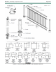
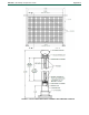
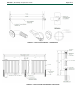
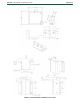
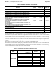
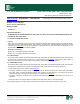
Table Of Contents

ESR-3485
|
Most Widely Accepted and Trusted Page 9 of 13
TABLE 1—MAXIMUM GUARDRAIL SYSTEM SPANS
1
PRODUCT
POST
HEIGHT
(INCH)
MAXIMUM
SPAN - IBC
(INCH)
MAXIMUM
SPAN - IRC
(INCH)
ALUMINUM RAILING SYSTEM WITH 3-INCH ALUMINUM POSTS
ATTACHED TO WOOD SUBSTRATE
2
42.000 68.300 91.313
ALUMINUM RAILING SYSTEM WITH 3-INCH ALUMINUM POSTS
ATTACHED TO CONCRETE SUBSTRATE
3
42.000 69.430 91.313
ALUMINUM RAILING SYSTEM WITH 2-INCH ALUMINUM POSTS
ATTACHED TO CONCRETE SUBSTRATE
3
42.000 66.000 91.313
ALUMINUM RAILING SYSTEM WITH 2-INCH ALUMINUM POSTS
WITH STANCHIONS MOUNTED TO CONCRETE SUBSTRATE
4
42.000 66.000 91.313
ALUMINUM RAILING SYSTEM AT 42 INCH HEIGHT WITH 2-INCH
SCREEN POST WITH L-BRACKETS ASSEMBLY ATTACHED TO
WOOD SUBSTRATE
8
96.000 72.000 91.313
ALUMINUM RAILING SYSTEM WITH ALUMINUM 3” POSTS AND
FASCIA BRACKET ASSEMBLY ATTACHED TO CONCRETE
SUBSTRATE
9
42.000 55.960 91.313
ADA HANDRAILS WITH 90° BRACKET ASSEMBLY ATTACHED TO
WOOD SUBSTRATE
5
N/A 72.000 72.000
ADA HANDRAILS WITH 90° BRACKET ASSEMBLY ATTACHED TO 3-
INCH ALUMINUM POST WITH BACKER PLATE
6
N/A 72.000 72.000
ADA HANDRAILS WITH MIDSPAN BRACKET ASSEMBLY ATTACHED
TO WOOD SUBSTRATE
5
N/A 72.000 72.000
ADA HANDRAILS WITH MIDSPAN BRACKET ASSEMBLY ATTACHED
TO 2-INCH ALUMINUM POST
6
N/A 72.000 72.000
MP400 MESH PANEL ASSEMBLY WITH EITHER 2-INCH OR 3-INCH
ALUMINUM POST
7
42.000 48.000 48.000
For SI: 1 inch = 25.4 mm
1
For Aluminum Railing System Series V800, C800, I800, A800, O800 and L800. For M600, the maximum span - IBC based on post and
assembly is as noted in Table 1, except the maximum span - IRC is 72 inches. Spans are from inside face to inside face of post.
2
Wood substrate must have a minimum specific gravity of 0.50 where each connection must use either four –
3
/
8
-inch x 6-inch long GRK RSS
wood screws for IBC application or four -
5
/
16
-inch x 6 inch-long GRK RSS wood screws for IRC application.
3
Concrete substrate must have a minimum compressive strength of 3700 psi where each connection must use four - 1/4-inch x 3-inch long
concrete anchor bolts supplied by Ultralox.
4
Connections of stanchion to stanchion mount and stanchion mount to the substrate must be designed by a registered design professional.
5
Wood substrate must have a minimum specific gravity of 0.49 where each connection must use three -
5
/
16
-inch x 4-inch long construction
lag screws.
6
Each connection to aluminum post must use three - No. 10 x 1 ½-inch long stainless steel TEK screws.
7
Each connection to aluminum post must use four - No. 8 x ¾-inch long stainless steel TEK screws.
8
Wood substrate must have a minimum specific gravity of 0.39 where each connection must use either four - No.9 x 3 ¼-inch SPAX screws
for IBC application or four - ¼-inch x 1 ¾-inch long TAPCON screws for IRC application. See Figure 5 for component details.
9
Concrete substrate must have a minimum compressive strength of 3900 psi where each connection must use four - ¼-inch x 3-inch long
concrete anchor bolts supplied by Ultralox. See Figure 6 for component details.
TABLE 2—COMPANY NAME AND PRODUCT NAME CORRELATION
COMPANY
NAME
ULTRALOX™
WILLIAMS
ARCHITECTURAL
PRODUCTS™
HARMONY
RAILING™
OPTIMA
®
RAILING
PRODUCT NAME
C800 C800 C800 -
V800 - V800 -
M600 - M600 -
I800 - I800 -
A800 - A800 -
O800 - - O800
L800 - L800 -
MP400 Mesh Panel - MP400 Mesh Panel -
ADA Handrail - - -