
Installation Instructions


Installing Your Furnace
18
Gas Supply and Piping
Gas control valve, within the furnace, is shipped with a seal over
the gas inlet tapping. Do not remove seal until ready to connect
piping.
WARNING: Danger of property damage, bodily
injury or death. Make sure the furnace is equipped
to operate on the type of gas available. Models
designated as natural gas are to be used with
natural gas only. Furnace designated for use with
liquefied petroleum (L.P.) gas rate orifices sized for
commercially pure propane gas. They cannot be
used with butane or a mixture of butane and
propane.
GAS SUPPLY
For Natural gas, the minimum inlet gas supply pressure for the
purpose of input adjustment is 5" water column. The Maximum
inlet gas supply pressure is 7" water column.
For L.P. gas, the minimum inlet gas supply pressure for the
purpose of input adjustment is 11" water column. The maximum
inlet gas supply pressure is 13" water column.
Gas pressure and input to the burners must not exceed the rated
input and pressure shown on the rating plate. On Natural Gas the
manifold pressure should be 4 inches water column. The manifold
pressure should be 10.5 inches water column for L.P. Gas. See
page 21 for operation above 2,000 feet altitude. Orifice change
may be required to suit gas supplied. Check with your local gas
supplier.
ORIFICE SIZES
Furnace Technical Information, page 25, shows the correct orifice
sizes for the different input ratings when using Natural or L.P. Gas.
GAS PIPING
The gas supply line must be of adequate size to handle the Btu/hr.
requirements and length of the run for the unit being installed.
Determine the minimum pipe size from Page 19, Fig. 23, basing
the length of the run from the gas meter or source to the unit.
All piping must comply with local codes and ordinances or with the
National Fuel Gas Code (ANSI Z223.1), whichever applies. In
Canada: Follow CAN 1-B149 Installation Code.
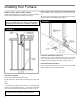
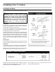
Refer to Page 18, Fig. 21, for the general layout at the unit. It
shows the basic fittings needed.
FIGURE 21
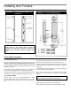
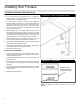
FIGURE 22 – Proper Piping Practice