Installation Guide & User Manual SoundFocus FM™ Classroom Amplification System Models CFM 300 & CFM 400 Transmitter Model T31 Receiver Model R800, Speaker Model SPK 800 MAN 045D ® Williams Sound Helping People Hear
SOUNDFOCUS™ CLASSROOM AMPLIFICATION SYSTEM MODEL CFM 300/400 INSTALLATION AND USER MANUAL Contents Page Quick Start Instructions 4 The T31 Transmitter 5 CHARGING INSTRUCTIONS TRANSMITTER OPERATION The R800 Receiver & SPK 800 Speaker 7 SPEAKER SETUP MINIMIZING FEEDBACK SPEAKER WIRING DIAGRAMS R800 FEATURES In Case Of Interference 10 Using Multiple Systems 10 In Case Of Difficulty 11 Optional Personal Receivers 12 Optional Mounting Kits 14 SB-3 WALL/CEILING MOUNT KIT SS-3 FLOOR STAND KIT
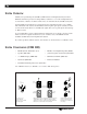
SYSTEM OVERVIEW Thank you for purchasing the SoundFocus FM™ Classroom Amplification System from Williams Sound Corp. Anyone needing auditory assistance to overcome background noise, reverberation, or distance from the sound source can benefit from the SoundFocus System. Your SoundFocus System has two principal parts: the transmitter and the receiver. Much like a miniature radio station, the transmitter and microphone pick up the sounds you want to hear and broadcast them over an FM radio signal.
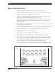
QUICK START INSTRUCTIONS 1. Charge the transmitter batteries first! See pages 10 and 11 for directions. 2. Plug the microphone into the transmitter mic jack. Clip the microphone onto a collar, lapel, or tie, as close to the speaker's mouth as is practical. 3. Turn the T31’s FM switch to ON. The transmitter can be placed in a pants pocket, or clipped onto a belt or waistband with the belt clip carry case. The microphone cord is the transmitting antenna.
USING THE T31 TRANSMITTER The T31 Transmitter’s microphone cord is the transmitting antenna. Do not bunch up the cord or wrap it around the transmitter. For maximum range, the cord should hang as straight as possible. The transmitter can be placed in a pants pocket, or clipped onto a belt or waistband. Make sure the transmitter is turned OFF when not in use. 1. Make sure there are two charged AA batteries in the transmitter. If batteries are not installed, see the section Battery Information on page 10.
USING THE R800 RECEIVERS & SPK 800 SPEAKERS The R800 is a combination FM receiver/amplifier/speaker. The SPK 800 is driven by the amplifier within the R800. Both are compact, self-contained, and portable. Most rooms will require just the two speakers, placed in either front corner of the room. For larger rooms, additional speakers may be added to the rear corners. MAIN FEATURES OF THE R800 RECEIVER/SPEAKER FM/Auxiliary Switch For normal use with the T31 Transmitter, the FM switch should be ON.
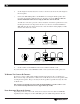
2. Set the height for both at about 4–5 feet above the floor, but not at the same height as the microphone. 3. Connect the SPK 800 Speaker to the R800 Receiver using the black speaker cable provided. (See Figure 6) Pull apart the two strands as necessary. Observe that one strand’s insulation is furrowed or ridged, while the other is smooth.
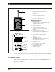
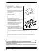
FIG. 7: R800 FEATURES R800 FRONT PANEL FEATURES 1 1. Flexible “Rubber Duckie” Antenna Threads onto the mounting stud on top of the receiver. 2. High Frequency Speaker Reproduces high frequencies. 3. Low Frequency Speaker Reproduces low frequencies. 2 R800 REAR PANEL FEATURES 3 1 Input FM Aux. 3 2 1 2 4 5 6 Remote Antenna Remote Speakers – FM/Auxiliary Switch Turns FM receiver on or off and allows input of auxiliary device signals. 2. FM Channel Switch Selects FM operating channel. 3.
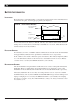
BATTERY INFORMATION INSTALLATION Open the battery compartment using a coin in the slot in the bottom of the transmitter. Press the batteries into place, observing proper polarity. (See Figure 8.) FIGURE 8: INSTALLATION OF BATTERIES Rear of Transmitter or Receiver Battery Compartment Note Proper Polarity – + + – Pry Slot Incorrect insertion of the battery is difficult, and may cause both mechanical and electrical damage not covered by the 5 year warranty to transmitters or receivers.
USING THE CHG 200A BATTERY CHARGER 1. Plug the CHG 200’s power supply into the Power Input on the charger’s side and a standard AC wall outlet. 2. Route the power cord around the Cord Hook (see figure at right). This will minimize strain on the cord and jack and insure that the power cord is not detached during charging. 3. Make sure the transmitter or receiver units to be charged are turned OFF. 4.
CHANGING FREQUENCIES If you experience FM signal interference, you can easily adjust your transmitter and receiver to a use different frequencies. CHANGING THE PFM T31 TRANSMITTER FREQUENCY 1. Open the battery compartment using a coin in the slot in the bottom of the transmitter. Remove the batteries. 2. Lift the flap up and to your left. The back of the transmitter case will open like a book, exposing the circuit board. 3. Use the diagram in Figure 10 to locate the channel selector switches.
USING MULTIPLE SYSTEMS When multiple systems are used in adjacent rooms, it is important to coordinate which channel is being used in each room to avoid interference. Follow the channel assignment diagram in Figure 11 to minimize the chances of interference. FIG.
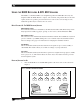
IF FEEDBACK OCCURS 1. Do not stand with the microphone directly in front of the speaker. Don’t try to set the volume while standing with the microphone in the “feedback zone.” Have someone help you adjust the volume. 2. Place the receiver and speaker as shown in Figure 5. Avoid pointing receivers or speakers directly perpendicular to a wall. 3. Turn the volume down. Remember, the system is not intended to play loudly. It should slightly boost the teacher’s voice above normal background noise levels.
OPTIONAL PERSONAL RECEIVERS The optional PFM R32 and PFM R31 Personal Receivers can both be used with the SoundFocus™ System. On each, the earphone cord is also the receiving antenna. Do not bunch up the cord or wrap it around the receiver. For best reception, the cord should hang as straight as possible. Make sure receivers are turned OFF when not in use. The channel selector on both receivers can be used to switch between an individual and a group channel.
8. Place the receiver in the belt clip case provided. The receiver can be placed in a pants pocket, or clipped onto a belt, harness, or waistband. USING THE PFM R31 RECEIVER: Receiver Model PFM R31 has two volume control knobs (one for the FM signal, one for environmental sounds), a microphone input jack, and an earphone output jack. 1. Make sure there are two charged AA batteries in the receiver. If batteries are not installed, see Battery Information on page 10. 2.
OPTIONAL MOUNTING KITS Williams Sound offers two optional mounting kits for use with the SoundFocus FM System. Use the SB-3 Wall/Ceiling Mount Kit to mount an R800 Receiver or SPK 800 Speaker to a wall or ceiling. The SS-3 Floor Stand Kit includes an adjustable stand and flange which allow you to elevate the R800 or SPK 800 as you choose. To order these optional components, contact your dealer or Williams Sound Corp. INSTALLING THE SB-3 WALL/CEILING MOUNT KIT 1.
FIG. 14: BRACKET 012 WALL MOUNTING Tension Screw Head Jam Nut Front of R800 If rotational adjustment is required, use a 7/16" open-end wrench to loosen the jam nut on the ballshaft. Rotate the receiver/ speaker and re-tighten the jam nut. INSTALLING THE SS-3 FLOOR STAND KIT 1. Align the three holes in the MFL 002 flange with the three pre-drilled holes in the base of the R800 or SPK 800. (See Figure 15.) FIG. 15: FLANGE PLACEMENT FIG.
WARRANTY The SoundFocus Classroom FM System is engineered and designed to provide you with many years of reliable service. Williams Sound warrants it against defects in materials and workmanship for FIVE (5) years EXCEPT FOR earphones, headphones, rechargeable batteries, chargers, cables, antennas, carry cases, and all other accessory products. Accessory products carry a 90 day warranty.
SOUNDFOCUS FM™ SYSTEM SPECIFICATIONS FM TRANSMITTER, MODEL PFM T31 Dimensions: Weight: Color: Battery Type: Operating Freq’s: Stability: Modulation: RF Output: FCC ID: Freq Response: Signal–Noise Ratio: Auto Gain Control: Transmit Antenna: Microphone: Controls: Mic Connector: 3-5/8" L x 2-3/8" W x 7/8" H (92.1 mm x 60.3 mm x 22.2 mm) 4.4 oz (125 g) with battery Royal blue, shatter-resistant polypropylene Two (2) AA 1.