Installation Guide & User Manual SoundFocus FM™ Classroom Amplification System Models CFM 801, CFM 802, CFM 803 and CFM 804 Transmitter Model T31 Receiver Model R802, Speaker Model SPK 016 MAN 097B ® Williams Sound Helping People Hear
SOUNDFOCUS™ CLASSROOM AMPLIFICATION SYSTEM MODEL CFM 802/804 INSTALLATION AND USER MANUAL Contents Page System Overview 4 System Components 4 Quick Start Instructions 5 The T31 Transmitter 6 CHARGING INSTRUCTIONS TRANSMITTER OPERATION The R802 Receiver & SPK 016 Speaker 7 R802 FEATURES RECEIVER/SPEAKER SETUP ADDITIONAL SPEAKERS USING AN ALTERNATE ANTENNA Team Teaching Applications 10 Battery Information 12 Changing Frequencies 14 Using Multiple Systems 15 In Case Of Difficulty 16 Opt
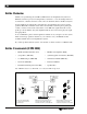
SYSTEM OVERVIEW Thank you for purchasing the SoundFocus FM™ Classroom Amplification System from Williams Sound Corp. Anyone needing auditory assistance to overcome background noise, reverberation, or distance from the sound source can benefit from the SoundFocus System. Your SoundFocus System has three principal parts: the transmitter, the receiver, and the speakers.
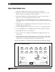
QUICK START INSTRUCTIONS 1. Charge the transmitter batteries first! See pages 10 and 11 for directions. 2. Plug the microphone into the transmitter mic jack. Clip the microphone onto a collar, lapel, or tie, as close to the speaker's mouth as is practical. 3. Turn the T31’s FM switch to ON. The transmitter can be placed in a pants pocket, or clipped onto a belt or waistband with the belt clip carry case. The microphone cord is the transmitting antenna.
USING THE T31 TRANSMITTER The T31 Transmitter’s microphone cord is the transmitting antenna. Do not bunch up the cord or wrap it around the transmitter. For maximum range, the cord should hang as straight as possible. The transmitter can be placed in a pants pocket, or clipped onto a belt or waistband. Make sure the transmitter is turned OFF when not in use. 1. Make sure there are two charged AA batteries in the transmitter. If batteries are not installed, see the section Battery Information on page 12. 2.
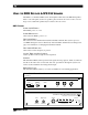
USING R802 RECEIVER & SPK 016 SPEAKERS THE The R802 is a combination FM receiver and amplifier which drives the SPK 016 Speakers. Most rooms will require just the two speakers, placed in the front corners of the room. For larger rooms, additional speakers may be added to the rear corners. R802 FEATURES POWER ON/OFF SWITCH Turns R802 power on or off. POWER LED INDICATOR Glows when the R802’s power is on. FM CHANNEL SWITCH The selected receiver channel must match the transmitter channel.
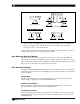
REMOTE ANTENNA CONNECTOR “F–type” connector for 75Ω Coaxial Antenna REMOTE SPEAKER CONNECTORS Connects R802 to the SPK 016s. Up to four speakers may be used. AC POWER SUPPLY Connects to 120VAC, 50/60 Hz outlet. FLEXIBLE “RUBBER DUCKIE” ANTENNA Threads onto the mounting stud on top of the receiver. RECEIVER/SPEAKER SET-UP 1: Place the SPK 016 Speakers at the front of the room as shown in Figure 6. 2: Set the height for both at about 4–5 feet above the floor, but not at the same height as the microphone.
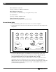
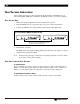
FIG. 7: SPEAKER WIRING DIAGRAMS RED BLK BLK RED BLK BLK RED RED RED BLACK BLACK RED RED BLACK BLACK RED RED BLACK ONE 4 OR 8 OHM SPEAKER FOUR 4 OR 8 OHM SPEAKERS Standard Configuration BLK BLK RED RED TWO 4 OHM SPEAKERS BLK BLACK RED RED BLACK BLACK RED RED BLACK BLK RED RED TWO 8 OHM SPEAKERS 4: Set the volume on the R802 below the level at which feedback occurs.
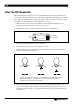
TEAM TEACHING APPLICATIONS Team teaching applications require an additional T31 Transmitter and R802 Receiver. A Team Teaching Kit (CFM 803) is available from Williams Sound to provide this capability. TEAM TEACHING SETUP 1. Make sure both T31 Transmitters are tuned to different frequencies. 2. Tune the R802 Receivers to frequencies that correspond to the T31 Transmitters. 3. Connect the R802 Receivers using the RCA to RCA Audio Cable (WCA 013). FIG.
FIG. 9: TYPICAL TEAM TEACHING CONFIGURATION Speaker Speaker Personal Receiver Transmitter Teacher 1 [Ch A] Personal Receiver Transmitter Teacher 2 [Ch B] R802 [Ch A] Speaker R802 [Ch B] Via Bridge In/Out Speaker Both Teacher 1 and Teacher 2 use T31 Transmitters and microphones to simultaneously transmit different FM radio signals to R802 Receivers on coreesponding frequencies. By connecting the R802s via Bridge In/Out jacks using an RCA to RCA cable, both teachers are heard through all speakers.
BATTERY INFORMATION INSTALLATION Open the battery compartment using a coin in the slot in the bottom of the transmitter. Press the batteries into place, observing proper polarity. (See Figure 10.) FIGURE 10: INSTALLATION OF BATTERIES Rear of Transmitter or Receiver Battery Compartment Note Proper Polarity – + + – Pry Slot Incorrect insertion of the battery is difficult, and may cause both mechanical and electrical damage not covered by the 5 year warranty to transmitters or receivers.
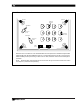
USING THE CHG 200A BATTERY CHARGER 1. Plug the CHG 200’s power supply into the Power Input on the charger’s side and a standard AC wall outlet. 2. Route the power cord around the Cord Hook. (See Figure 11.) This will minimize strain on the cord and jack and insure that the power cord is not detached during charging. FIGURE 11: USING THE CHG 200A BATTERY CHARGER Charging Pins Charging Contact Holes Charging Indicators Power Input Cord Hook 3.
CHANGING FREQUENCIES If you experience FM signal interference, you can easily adjust your transmitter and receiver to a use different frequencies. CHANGING THE PFM T31 TRANSMITTER FREQUENCY 1. Open the battery compartment using a coin in the slot in the bottom of the transmitter. Remove the batteries. 2. Lift the flap up and to your left. The back of the transmitter case will open like a book, exposing the circuit board. 3. Use the diagram in Figure 12 to locate the channel selector switches.
USING MULTIPLE SYSTEMS When multiple systems are used in adjacent rooms, it is important to coordinate which channel is being used in each room to avoid interference. Follow the channel assignment diagram in Figure 13 to minimize the chances of interference. FIG. 13: MULTIPLE SYSTEM CHANNEL PLAN 72.1 MHz 72.3 MHz 72.5 MHz 72.7 MHz 72.9 MHz 74.7 MHz 75.3 MHz 75.5 MHz 75.7 MHz 75.9 MHz Room 1 Room 3 Room 5 Room 7 Room 9 Room 11 Room 13 Room 15 Room 17 Room 19 74.7 MHz 75.3 MHz 75.
IN CASE OF DIFFICULTY IF NO SOUND IS PRODUCED 1. Make sure the batteries are fresh or completely charged and that the “plus” and “minus” terminals are installed correctly in the transmitter. 2. Make sure the transmitter FM switch is ON and the MIC switch is ON. 3. Make sure the microphone is plugged into the T31 Transmitter 4. Make sure the R802’s power switch is ON. 5. Make sure the transmitter and receiver are set to the same channel. 6. Move the transmitter and receiver closer together.
IF OTHER PROBLEMS OCCUR 1. If the rechargeable batteries will only work for a short period of time (less than 1 hour) even after they are fully charged, they must be regenerated. Leave them in the transmitter or personal receiver with the unit turned on for 5 - 6 hours. Then turn the transmitter or personal receiver off, place it in the charger, and charge for 14 - 16 hours. This should restore normal battery life.
OPTIONAL PERSONAL RECEIVERS The optional PFM R32 and PFM R31 Personal Receivers can both be used with the SoundFocus™ System. On each, the earphone cord is also the receiving antenna. Do not bunch up the cord or wrap it around the receiver. For best reception, the cord should hang as straight as possible. Make sure receivers are turned OFF when not in use. The channel selector on both receivers can be used to switch between an individual and a group channel.
8. Place the receiver in the belt clip case provided. The receiver can be placed in a pants pocket, or clipped onto a belt, harness, or waistband. USING THE PFM R31 RECEIVER: Receiver Model PFM R31 has two volume control knobs (one for the FM signal, one for environmental sounds), a microphone input jack, and an earphone output jack. FIGURE 14: R31 TOP VIEW FM Volume On Indicator Mic Jack FM EAR FM Indicator FM Off On Max Min Mic MIC Max Mic Volume Mic Jack 1.
OPTIONAL MOUNTING KITS Williams Sound offers two optional mounting kits for use with the SoundFocus FM System. Use the SB-3 Wall/Ceiling Mount Kit to mount an SPK 016 Speaker to a wall or ceiling. The SS-3 Floor Stand Kit includes an adjustable stand and flange which allow you to elevate the SPK 016 as you choose. To order these optional components, contact your dealer or Williams Sound Corp. INSTALLING THE SB-3 WALL/CEILING MOUNT KIT 1.
FIG. 17: CEILING MOUNTING FIG. 18: WALL MOUNTING Tension Screw Head Jam Nut Front of SPK 016 After initial installation, the ball will slowly compress under pressure. Check the tension screw after 15 minutes and re-tighten if necessary. DO NOT OVER TIGHTEN. If rotational adjustment is required, use a 7/16" open-end wrench to loosen the jam nut on the ballshaft. Rotate the receiver/ speaker and re-tighten the jam nut. INSTALLING THE SS-3 FLOOR STAND KIT 1.
WARRANTY The Williams Sound SoundFocus FM™ Classroom Amplification System is engineered and designed to provide you with many years of reliable service. Williams Sound warrants it against defects in materials and workmanship for FIVE (5) years EXCEPT FOR earphones, headphones, rechargeable batteries, chargers, cables, antennas, carry cases, and all other accessory products. Accessory products carry a 90 day warranty.
SOUNDFOCUS FM™ SYSTEM SPECIFICATIONS SOUNDFOCUS FM TRANSMITTER, MODEL PFM T31 Dimensions: 3-5/8" L x 2-3/8" W x 7/8" H (92.1 mm x 60.3 mm x 22.2 mm) Weight: 4.4 oz (125 g) with battery Color: Royal blue, shatter-resistant polypropylene Battery Type: Two (2) AA 1.5 V Non-rechargeable Alkaline batteries (BAT 001), 70 mA nominal current drain, 12 hours approx. life (OR) Two (2) AA 1.5 V Ni-Cad Rechargeable batteries (BAT 026), 70 mA nominal current drain, 10 hours per charge approx.
BATTERY CHARGER, MODEL CHG 200A Dimensions 6-3/4" L x 3-5/8" W x 2-1/8" H (17.15 cm x 9.2 cm x 5.4 cm) Weight: 9.28 oz (260 g) Color: Black, pebble grain texture with white legends Power Input: 6 VDC Power Transformer: 110 V, polarized, 60 Hz, 1.8 VA Indicators: Charging in process OPTIONAL PERSONAL RECEIVERS, MODELS PFM R31 & PFM R32 Dimensions 3-5/8" L x 2-3/8" W x 7/8" H (92.1 mm x 60.3 mm x 22.2 mm) Weight: 4.