Installation Guide & User Manual SoundPlus® Two–Channel Infrared System Large Area Infrared Listening System Modulator Model WIR MOD 112 Transmitter Model WIR TX6 Receiver Models WIR RX5, RX6 MAN 064 ® Williams Sound Helping People Hear
SoundPlus® Two–Channel Infrared Listening System Installation Guide and User Manual Contents Page System Overview 4 Installation Procedures Step 1: TX6 Transmitter Setup Step 2: TX6 Power Wiring Step 3: Baseband Cable Connection Step 4: MOD 112 Modulator Installation Step 5: Testing The System 5 8 9 9 11 Controls and Features MOD 112 Front Panel MOD 112 Rear Panel TX6 Transmitter 12 14 15 Receiver Instructions 16 Receiver Management 17 Troubleshooting 17 Warranty 18 Specifications 19 Note
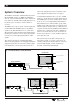
from radio equipment and does not interfere with radio equipment. No FCC license is required. System Overview The Williams Sound Two–Channel Infrared System, Model TX600 consists of a MOD 112 Modulator and one or more TX6 Transmitters (also called emitters) which use invisible infrared (IR) light waves to broadcast speech or music to wireless infrared receivers. The MOD 112 accepts a variety of audio inputs and sends 95 kHz and 250 kHz frequency modulated signals to the TX6 Transmitter via a coaxial cable.
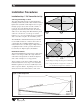
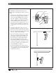
Installation Procedures Figure 2: Infrared Illumination Patterns Installation Step 1: TX6 Transmitter Set-Up Selecting a Mounting Location 25° 25° 250 ft. 130 ft. The most important principle to understand when installing an infrared system is that invisible infrared light behaves just like visible light. It does not pass through opaque objects such as walls, curtains, or people. It does pass through windows and door openings and can bounce and scatter off reflective walls, floors, and ceilings.
Infrared light reflects off most surfaces and scatters, which increases the coverage area. Rough surfaces tend to absorb infrared light, minimizing reflections, and limiting coverage to the direct illumination pattern. It’s helpful to think of the IR transmitter as an invisible floodlight. You want to aim it so listeners are “flooded” with infrared light. Listening areas of more than 5,000 square feet will require two or more TX6 Transmitters for complete coverage.
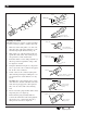
Figure 4: Mounting The TX6 Fig. 4a: SB-3 Wall/Ceiling Mount The TX600 Two–Channel Infrared System includes a kit for mounting the TX6 to a wall or ceiling. 1. Use the 5/32" allen wrench to loosen the tension bolt in the clamp assembly enough to release the ball. DO NOT unscrew the tension bolt completely. Using the mounting plate as a template, mark the hole locations on the mounting surface.
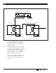
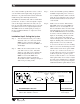
Figure 5: TX6 Transmitter Wiring Detail MOD 112 Modulator Baseband Out Model WIR MOD112 Two-Channel Infrared System Modulator TFP 016 Power Supply Baseband In Baseband In Baseband Out Baseband Out Williams Sound ® Helping People Hear Williams Sound ® Helping People Hear To Additional TX6 Transmitters TX6 Transmitter TX6 Transmitter TFP 010 Power Supply TFP 010 Power Supply is on.
Installation Step 3: Baseband Cable Connection Installation Step 4: MOD 112 Modulator If You’re Using One Transmitter: The Modulator is usually located with the sound system amplifier or mixer for easy access to an audio input signal. For portable systems, the modulator can be placed near the transmitter or wherever is most convenient. Step 1: Determine the length of RG-58 coaxial cable needed to reach from the transmitter to the modulator unit.
6b Figure 6: BNC Connector Assembly Washer 7.92 mm (± .25) .312 in. (± .01) Nut Gasket Nut Cable Jacket Washer Plug Assembly Gasket 6c Clamp Contact Clamp positioned against Cable Jacket Assembly Procedure 6d The BNC Connector consists of a plug assembly, a contact, a clamp, a gasket, a washer, and a nut. Clamp Collar 1. Slide nut, washer and gasket over cable end; then strip outer cable jacket using the recommended strip-length dimension in fig. 6b. 2.
25 V, 70 V, and 100 V speaker lines can be connected to the balanced line inputs using an appropriate attenuator. “T” pads made with resistors yield better fidelity than speaker matching transformers. The MOD 112 transmits audio with excellent fidelity. Therefore, be sure to connect its inputs to signal sources that supply audio that is the best your system can offer. The signal should not be processed by an equalizer used for an accompanying PA system.
Channel 1 and 2 each have individual Level Controls, Level Indicators and Carrier On Indicators. They function independently and identically for each channel. Controls and Features MOD 112 Front Panel Power Switch Level Indicator Turns the entire system on and off. The associated wall mounted power supply stays on at all times and may operate continuously. There is no “wear out” mechanism. Bar graph level indicator shows audio level in 3 dB steps at input of audio level processing circuit.
allowing another 30 minutes before the carrier can again go off. After the carrier has automatically gone off, audio sufficient to light the -21 level indicator light will turn the carrier back on immediately. Audio Processor Switch Selects one of the two modes available. Limit Mode The audio processor has little effect on low level sound. As the level increases, reaching the level to light the red +6 light on the level indicator, no further increase in transmitted level is permitted.
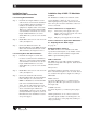
Figure 9: MOD 112 Modulator Rear Panel Input 1 and Input 2 Power In These main inputs to the modulator accept any low impedance microphone or line level signal. 21 VAC to 26 VAC only, 50 or 60 Hz. (TFP 016 Power Supply) Current consumption is approximately 130 mA. Baseband Output Carriers tones of 95 kHz and 250 kHz are provided at this BNC connector. One 50 Ω device may be connected here using RG-58 cable. Additional devices may also be connected in series.
Baseband Output TX6 Transmitter Carrier tones of 95 kHz and 250 kHz are provided at this BNC connector. One 50 Ω device may be connected here using RG-58 cable. Additional devices may be connected by “looping through” the connected device or by means of a suitable distribution amplifier. The output impedance is 50 Ω. Frequency accuracy is approximately ± .005%. Deviation is ± 50 kHz, maximum. Average deviation is dependent on program material and whether Limit mode or Compress mode is selected.
Receiver Instructions Step 3: Turn the receiver on by rotating the volume control knob clockwise. Two Channel IR Receiver Model WIR RX5 Step 4: Adjust the tone to your preference using the slide switch tone control. To avoid draining the battery, make sure the receiver is turned off when not in use. Make sure the “eye” on the front of the receiver is not covered up when in use. The receiver is intended to be worn on the front of the body, hanging from the lanyard attached to the receiver.
Receiver Management Different types of facilities will use different approaches for receiver management and earphone sanitation. Following are some alternatives that other customers have used successfully: 1. Regular users purchase their own receiver and take care of their own batteries and earphone. 2. Some facilities label the receiver and earphone with the names of regular users so each person uses the same receiver and earphone. 3. Ushers issue receivers to people who request them.
Warranty Williams Sound Transmitters and Receivers are warranted against defects in workmanship and materials for FIVE YEARS. Microphones, earphones, cables, carry cases, rechargeable batteries and chargers are warranted against defects in workmanship and materials for 90 DAYS. This warranty does not extend to intentional or accidental physical damage. This warranty applies only to products returned to Williams Sound for service.
SoundPlus™ Multi–Channel Infrared System Specifications Two–Channel Infrared Modulator, Model MOD 112 Dimensions, Weight: 8.45" (21.5 cm) W x 8.18" (20.8 cm) D x 1.72" (4.4 cm) H, 3 lbs. (1.
Infrared Emitter, Model TX6 Dimensions, Weight: 11.125" (28.3 cm) W x 8.125" (20.6 cm) H x 3.25" (8.3 cm) D, 3.25 lbs. (1.6 kg) Color: Black epoxy paint with white legends, red acrylic window Wall Mount: Omnidirectional mount included for wall and ceiling mounting. Tripod Mount: Optional SS-2 Tripod Stand Kit available Power: External power supply, 24 VAC, 50 or 60 Hz, 50 VA, 0.9 A nom. current drain Transmitter shuts off when baseband signal is not present Operating Req.