Installation Guide & User Manual SoundPlus ® WIR TX850 Infrared System, Selectable 95 kHz or 250 kHz Carrier Large Area Infrared Listening System Modulator Model MOD 111 Emitter Model WIR TX8 Receiver Models WIR RX7, RX8 MAN 083D ® Williams Sound Helping People Hear
SOUNDPLUS ® WIR TX850 INFRARED LISTENING SYSTEM, SELECTABLE 95 KHZ OR 250 KHZ CARRIER INSTALLATION GUIDE AND USER MANUAL Contents Page SYSTEM OVERVIEW 4 INSTALLATION PROCEDURES 6 STEP 1: STEP 2: STEP 3: STEP 4: STEP 5: TX8 EMITTER SETUP TX8 POWER WIRING BASEBAND CABLE CONNECTION MOD 111 MODULATOR SETUP TESTING THE SYSTEM CONTROLS AND FEATURES 14 MOD 111 FRONT PANEL MOD 111 REAR PANEL TX8 EMITTER PANEL RECEIVER INSTRUCTIONS 19 TROUBLESHOOTING 21 WARRANTY 22 SPECIFICATIONS 23 NOTE: TAKING
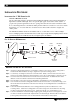
SYSTEM OVERVIEW The Williams Sound WIR TX850 System consists of a MOD 111 Modulator and one or more TX8 Emitters (also called emitters) which use invisible infrared (IR) light waves to broadcast speech or music to wireless infrared receivers. The MOD 111 accepts a variety of audio inputs and sends either a 95 kHz or 250 kHz frequency modulated signal to the TX8 Emitter via coaxial cable. The emitter emits invisible infrared light into the listening area.
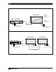
FIGURE 1: TYPICAL SYSTEM CONFIGURATIONS Baseband Present Indicator (Visible From Below) TX8 Transmitter MOD 111 Modulator 3 2 4 5 6 1 Baseband Out Phones 7 8 Audio Level CXR 9 Audio Infrared Test Out Limit 0 10 CH 1 Level Power Power On Indicator (Visible From Below) Williams Sound MOD 111 Selectable 95/250kHz Infrared System Modulator Compress Baseband In Power Supply 120 VAC (US): TFP 016 230 VAC (CE): TFP 027 Power Supply 120 VAC (US): TFP 010 230 VAC (CE): TFP 027 FIGURE 1B: USING AN
INSTALLATION PROCEDURE INSTALLATION STEP 1: TX8 EMITTER SET-UP SELECTING A MOUNTING LOCATION The most important principle to understand when installing the TX850 system is that invisible infrared light behaves just like visible light. It does not pass through opaque objects such as walls, curtains, or people. It does pass through windows and door openings and can bounce and scatter off reflective walls, floors, and ceilings.
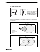
FIG. 2B: WALL OR CEILING MOUNT Figure 2a: Mounting the TX8 on to a wall with the BKT 024. Tip: To keep the TX8 level, rotate the tension screw (Fig. 2A) so it rests on top of the bracket. B. A. Figure 2b: Mounting the TX8 on to a ceiling with the BKT 024. ILLUMINATION PATTERNS The infrared illumination pattern from a single emitter is cone-shaped, with a 50° angle. The horizontal and vertical patterns are identical. Figures 3, 4, and 5 show top and side views of coverage patterns.
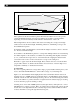
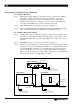
FIGURE 5: SIDE PERSPECTIVE 120' TX8 Center m ter Bea Of Emit 30' SCREEN 6' STAGE These patterns are the direct radiation pattern. The infrared radiation does not drop to zero outside the illustrated patterns; it decreases. It still may be useable at a greater distance, depending on receiver sensitivity and the reflection characteristics of the room. Infrared light reflects off most surfaces and scatters, increasing the coverage area.
INSTALLATION STEP 2: TX8 POWER WIRING FOR U.S. APPLICATIONS: The TX8 Emitter is supplied with a low-voltage wall transformer power supply (TFP 010). Two-conductor 18 ga. power cord is included with the emitter. FOR APPLICATIONS OUTSIDE THE U.S. REQUIRING 240 VAC MAINS SUPPLY: Use the wall transformer power supply, model TFP 027. Secondary Specifications: 24 VAC, 35 VA, 50/60 Hz.
INSTALLATION STEP 3: BASEBAND CABLE CONNECTION IF YOU ARE USING ONE EMITTER: Step 1: Determine the length of RG-58 coaxial cable needed to reach from the emitter to the modulator unit. The modulator is usually located with the other sound equipment to simplify audio connections. 100 feet (30 m) of coaxial cable is included with each emitter. You will need to cut it to length. Additional RG-58 coax can be added. Make sure you leave some slack at each end.
7B FIGURE 7: BNC CONNECTOR ASSEMBLY Washer 7.92 mm (± .25) .312 in. (± .01) Nut Grooved Side Gasket (note groove) Nut Cable Jacket Washer Plug Assembly Gasket 7C Clamp Contact Clamp positioned against Cable Jacket 7D ASSEMBLY PROCEDURE Clamp Collar The BNC Connector consists of a plug assembly, a contact, a clamp, a gasket, a washer, and a nut. 1. Slide nut, washer and gasket over cable end; then strip outer cable jacket using the recommended strip-length dimension in fig. 7b.
INSTALLATION STEP 4: MOD 111 MODULATOR SETUP LOCATION The Modulator is usually located with the sound system amplifier or mixer for easy access to an audio input signal. For portable systems, the modulator can be placed near the emitter or in another convenient location. (The SS-6 Stand Kit is available for portable systems.) POWER CONNECTION FOR U.S. APPLICATIONS: Step 1: Connect the power supply to the 3-pin Molex connector located on the rear of the MOD 111. (See Figure 8.
UNBALANCED LINE A 1/4 inch Tip-Sleeve (2 conductor) phone plug is used. 8 Ω speaker lines can be connected to the balanced line input. It is usually better NOT to connect to the sleeve of the plug and thus avoid creating a ground loop. A 25 V, 70 V, or 100 V speaker line can be connected to the balanced line input using an appropriate attenuator. “T” pads made with resistors yield better fidelity than speaker matching transformers. Note: The MOD 111 transmits audio with excellent fidelity.
CONTROLS AND FEATURES MOD 111 FRONT PANEL POWER SWITCH Turns the entire system on and off. The associated wall mounted power supply stays on at all times and may operate continuously. There is no “wear out” mechanism. POWER ON INDICATOR Indicates actual operation of modulator. Does not indicate status of power supply. LEVEL CONTROL Controls level of audio signal. The control is connected between the input amplifier and the audio level processing circuit.
AUDIO PROCESSOR SWITCH Selects one of the two modes available. LIMIT MODE The audio processor has little effect on low level sound. As the level increases, reaching the point at which the red +6 LED lights, no further increase in transmitted level is permitted. This is necessary to prevent distortion in receivers and prevent interference with other channels. Limit produces a very natural sound, and is most desirable for music. High quality speech signals are also very pleasant to listen to.
FIGURE 10: MOD 111 MODULATOR REAR PANEL Input The input to the modulator accepts any low impedance microphone or line level signal. Baseband Output Carrier tones of 95 kHz and 250 kHz are provided at this BNC connector. One 50 Ω device may be connected here using RG-58 cable. Additional devices may also be connected in series.
FIGURE 11: MOD 111 CIRCUIT DIAGRAM OUT AMPL W/DEEMPH MIC 1 2 COMPRESS + 15 V 3 LOW PASS FILTER PREEMPHASIS INPUT LINE T TS RS – LIMIT LEVEL DETECTOR 10 LIGHT BAR GRAPH PHONES CARRIER SYNTH CARRIER TIMER DEV. CAL.
FIGURE 13: TX8 EMITTER REAR PANEL Wall/Ceiling Mount Template Set of threaded holes for use with the BKT 024 (Pana-Vise) bracket. Multi-Channel Infrared Transmitter Williams Sound ® Helping People Hear CAUTION RISK OF ELECTRIC SHOCK DO NOT OPEN Williams Sound Corp., Minneapolis, Minnesota, USA Made in U.S.A. WARNING: TO REDUCE THE RISK OF FIRE OR ELECTRIC SHOCK DO NOT EXPOSE THIS EQUIPMENT TO RAIN OR MOISTURE.
RECEIVER INSTRUCTIONS IR RECEIVER MODELS WIR RX7 & WIR RX8 Make sure the “eye” on the front of the receiver is not covered up when in use. The receiver is intended to be worn on the front of the body, hanging from the lanyard attached to the receiver. The receiver will not work if it is placed in a pocket or purse. A variety of earphones, headphones, or neckloop telecoil couplers can be used with both RX7 and RX8 Receivers.
RECEIVER MANAGEMENT Different types of facilities will use different approaches for receiver management and earphone sanitation. Below are some options that customers have used successfully. 20 Regular users purchase their own receiver and take care of their own batteries and earphone. Some facilities label the receiver and earphone with the names of regular users so each person uses the same receiver and earphone. Ushers issue receivers to people who request them.
TROUBLESHOOTING NEITHER TX8 INDICATOR LIGHT IS ON (FIGURES 1A AND 13). Make sure the wall transformer is plugged into the emitter and the power switch or any remote power switch is on. Make sure the electrical outlet is on. Make sure the 24 VAC power supplies are working. ONLY TX8’S POWER INDICATOR LED COMES ON (FIGURES 1A AND 13). Make sure the MOD 111 is on. Make sure the baseband cable is connected properly. Check to see if the carrier light on the MOD 111 is on.
WARRANTY Williams Sound infrared modulators, emitters and receivers are warranted against defects in workmanship and materials for FIVE YEARS. Microphones, earphones, cables, carry cases, rechargeable batteries and chargers are warranted against defects in workmanship and materials for 90 DAYS. This warranty does not extend to intentional or accidental physical damage. This warranty applies only to products returned to Williams Sound for service.
SoundPlus® WIR TX850 Infrared System Specifications SELECTABLE CHANNEL INFRARED MODULATOR, MODEL MOD 111 Dimensions, Weight: 8.45" (21.5 cm) W x 8.18" (20.8 cm) D x 1.72" (4.4 cm) H, 3 lbs. (1.
FRONT PANEL: Power Indicator: Red LED, visible from bottom through vent holes, lower right Baseband Indicator: Red LED, visible from bottom through vent holes, lower left REAR PANEL: Mounting Holes: One set of threaded holes for use with the BKT 024 mounting bracket (included) Two threaded holes on sides of the cabinet for Tripod Stand Kit Baseband Input: BNC connector, 50 Ω, 50 kHz to 500 kHz carriers, 100 mV nominal per carrier, 10 V RMS maximum aggregate baseband amplitude Baseband Output: BNC c